ezPLA - C64 PLA replacement PCB
ezContents 2 September 2021
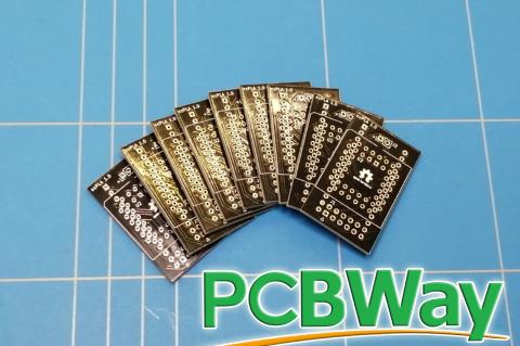
A while back I created a prototype board for the PLA replacement chip for C64. It was time to make a PCB out of it. In this blog post I will describe the steps that I did to design the PCB using KiCad and manufacture it using PCBWay prototype service.
Atari 800XL PCB - soldering and troubleshooting
ezContents 16 March 2021
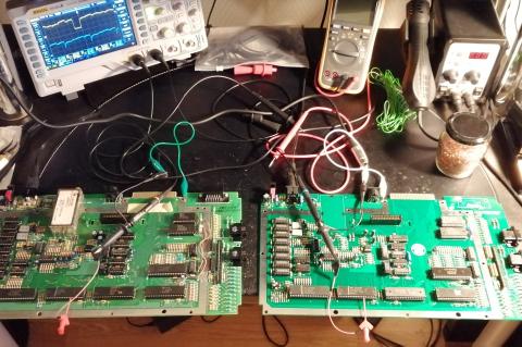
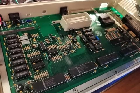
After collecting all the components needed for the Atari board it was finally time to solder them. But what are the chances that the project would work on first attempt? In my case it didn't and I will describe here my process of troubleshooting.
Atari 800XL bill-of-materials (BOM)
ezContents 15 January 2020
In my previous blog, I have written a bit about the remake of the PCB board for Atari 800XL computer. Now I will describe the process of acquiring all the parts needed to build it.
Atari 800XL PCB remake
ezContents 24 November 2019
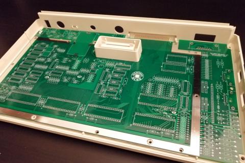
As a child I have owned an Atari 800XL. This 8-bit computer always had a special place in my heart. After almost 35 years I have decided to dive a bit deeper into the circuitry of this now called retro computer. What better way to start than to remake the PCB from scratch.
MiSTer USB Hub 2.1 - SMD soldering
ezContents 15 November 2019
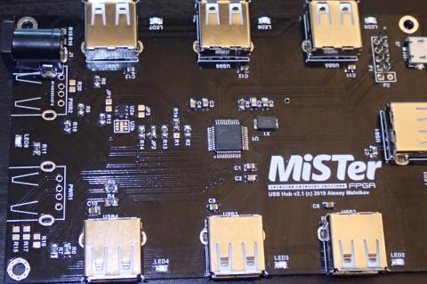
When you need to connect more then one USB device to your DE10-Nano FPGA board then you need to use a powered USB hub. It is possible to use normal hub, but it is way cooler to connect the one that is custom designed for the MiSTer project.
MiSTer IO Board 5.6 - Assembly
ezContents 7 October 2019
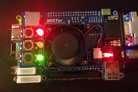
MiSTer project that is installed on the DE10-Nano board can only output video using the on-board HDMI connector. However if you want to get the real retro gaming experience then you can attach the MiSTer IO Board. Among other things, this add-on board let's you output 15KHz analog RGB video and audio signals that will let you connect to a CRT monitor. This blog post describes how to build such a board.
MiSTer IO Board - PCB
ezContents 22 September 2019
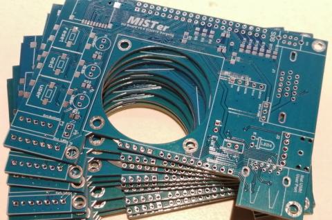
In order to connect your DE10-Nano board to VGA or other RGB output, you need an I/O Board. This PCB board and assembly instructions are available on the GitHub pages of the MiSTer project.
PCB LED Xmas Tree
ezContents 11 December 2018
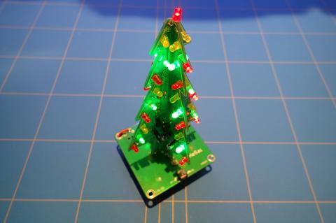
If you want to save your valuable space and don’t want to put a real Xmas tree in your room, there is always an option to make one out of PCB and LEDs and during the process learn something about electronics.
Etching 555 astable timer PCB
ezContents 14 April 2017
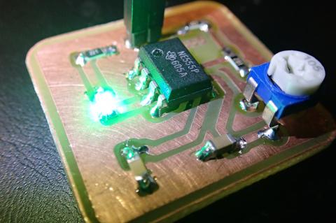
There is something about blinking leds. Numerous projects are created with the 555 timer chip. To continue the tradition I will describe in detail the creation of a 555 astable timer board that was designed in the previous blog post.
Designing PCB with KiCad
ezContents 14 April 2017
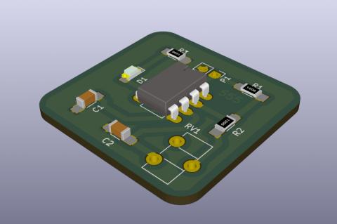
KiCad is a great schematic and PCB design tool. It is easy to learn and fun to use, above all it is free. In this blog post we are going to design a simple circuit based on the 555-timer chip in astable mode.