As a child I have owned an Atari 800XL. This 8-bit computer always had a special place in my heart. After almost 35 years I have decided to dive a bit deeper into the circuitry of this now called retro computer. What better way to start than to remake the PCB from scratch.
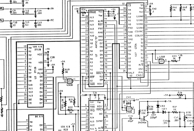
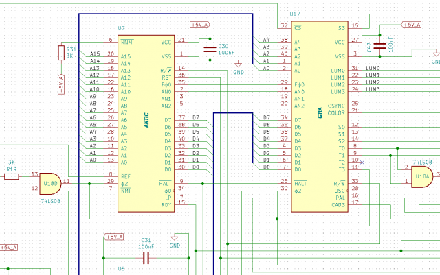
For that purpose I have used the free Open Source EDA - KiCad 5.1. This package has a tool called EESchema where I was able to recreate the schematics. I based it on the original ones published by Atari in the 800XL Service manual. Which can still be found on the Internet Archive pages: https://archive.org/details/Atari800XLServiceManual. On the last pages you can find full schematics of the machine. A part of it is shown in the screenshot below.
I will not go in detail of the process on how I have created the schematics and PCB, this is subject for another post (or maybe even a series). But I can say it was a fun process and in my experience this is the best way to learn KiCad in full detail.
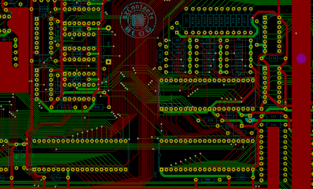
When the schematics were done I could start with the design of the PCB. In KiCad this can be done with pcbnew tool. The original PCB had 2 layers, so I have sticked with that. I was also trying to stay as close as possible to the original, including all the drill holes and the placement of the components.
After finishing the layout it was time to manufacture the PCB. I have selected PCBWay as I had used their services in the past and was satisfied with them.
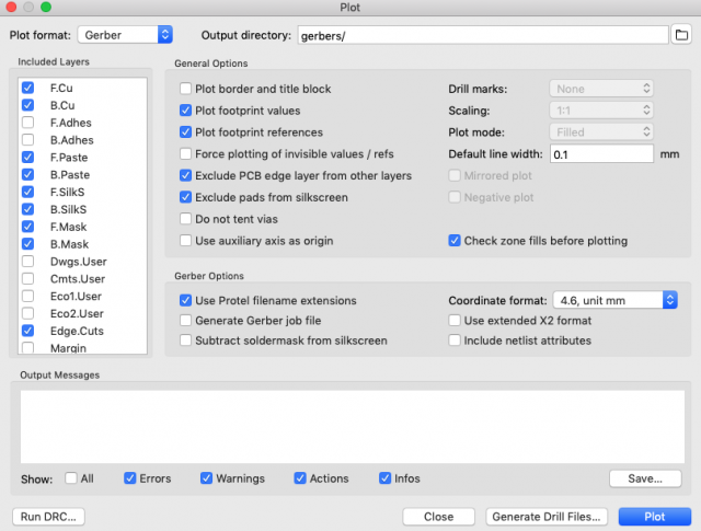
First step is to create the Atari 800XL Gerber files from the design. This can be done with the "Plot" function inside the File menu of pcbnew. PCBWay also have a page on how to do this. It is for KiCad 4, but for version 5 is it almost the same. Keep the defaults and make sure you have selected the correct layers.
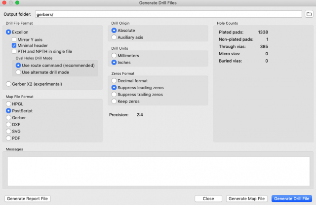
Now you need to generate the drill files. The only difference from version 4 is that KiCad 5 generates 2 files for the drill holes. One is for PTH (plated though holes) and the other for NPTH (Non-plated through holes). PCBWay have no problem when you include both of them. Make sure you have selected "Minimal header"and "Suppress leading zeros"
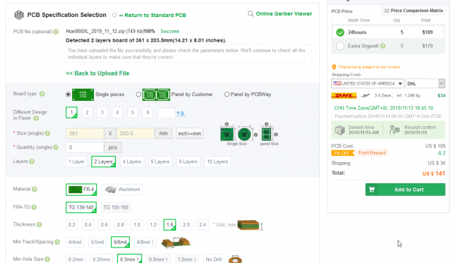
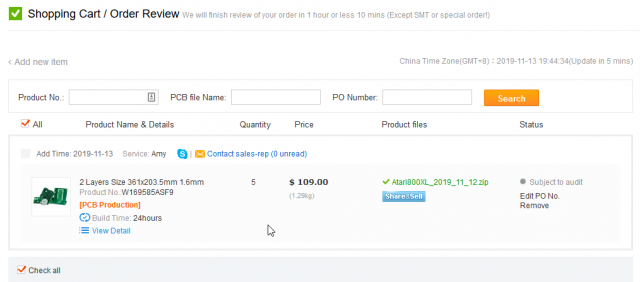
After you are done with the generation of the files, create a zip file. This file you can upload on the PCBWay order page. It will automatically calculate the board size and the price for 5 pieces.
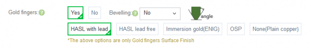
The only extra option that I have selected were the gold fingers for the connectors on the board. Note: If you want them truly gold, you need to select ENIG option. This one I have actually missed and my gold fingers got a HASL with lead treatment.
The total costs where as low as $109. The shipping costs with DHL to the Netherlands were $37. In the screenshot about you can see the shipping costs to USA.
After completing the order, the review and manufacturing process have started.
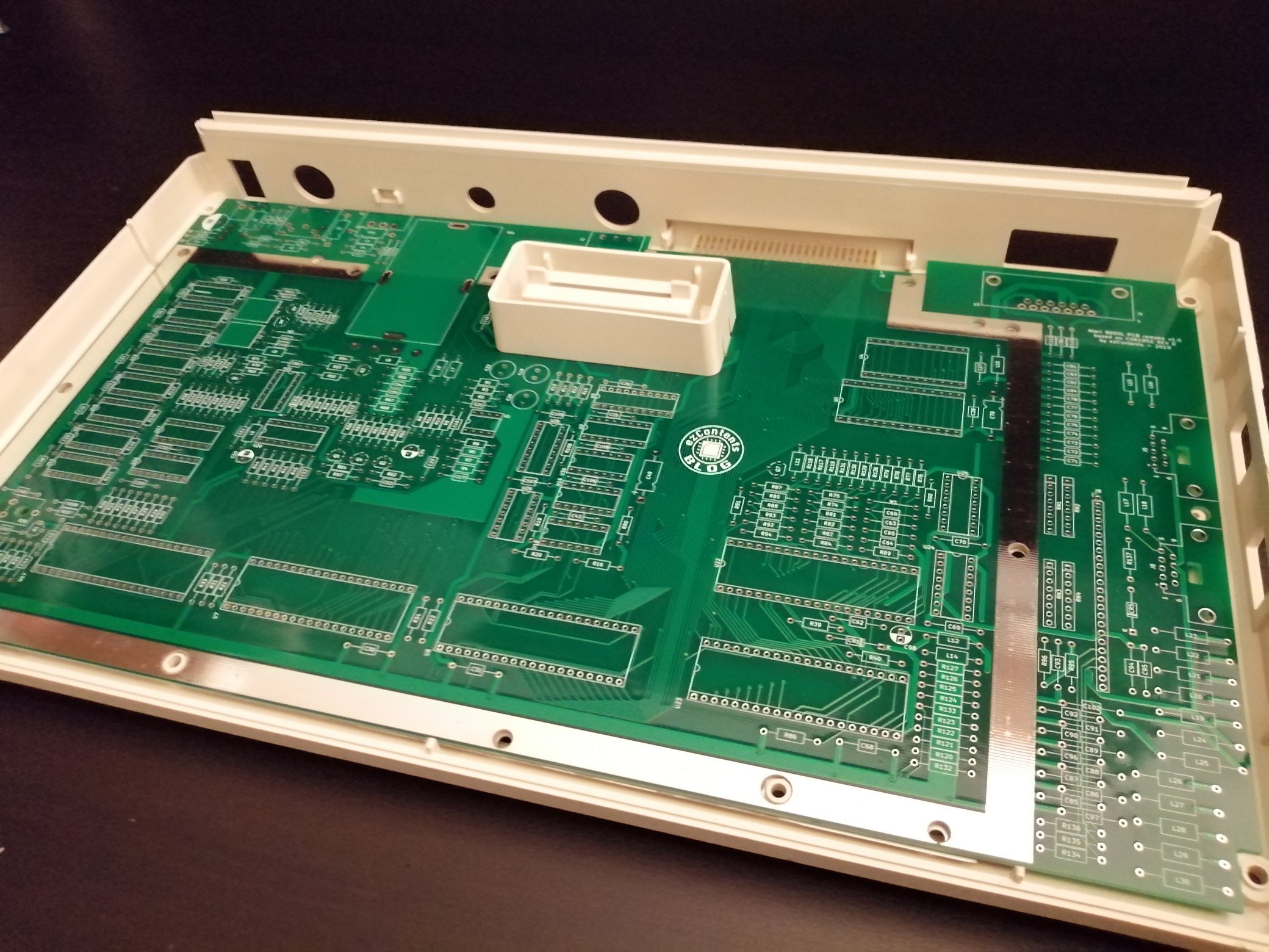
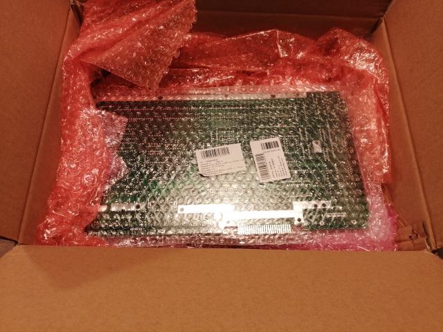
Only after 5 days the PCBs got delivered! My first impressions while unpacking were very good. They very well wrapped inside protective bubble wrapping.
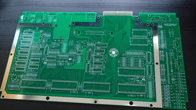
The PCBs looked also very good. I have selected green solder mask (as the original).
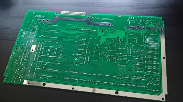
The back of the PCB looked fine too. The original Atari PCB did not have a silk screen on the back, so I also did not add anything to the remake version.
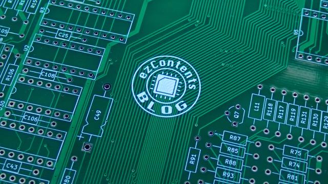
Close-up of some thin PCB traces and the silk screen looked good as well. I have added this custom ezContents blog logo and it turned out exactly as expected.
I have to conclude that I am very satisfied with the services of PCBWay. They promptly answered all of my questions that I had by mail. For sure I will be using their services in the future.
If you decide to order your PCBs and use this link and register you will get $5 discount on your order.
The Atari 800XL PCB project is still in progress. At the moment I am still waiting for some of the components to be delivered and will be starting to solder soon. Then will come the true test if the schematics and my PCB design that I have created will work.