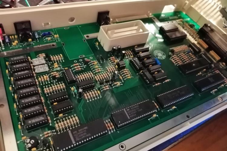
In my previous blog, I have written a bit about the remake of the PCB board for Atari 800XL computer. Now I will describe the process of acquiring all the parts needed to build it.
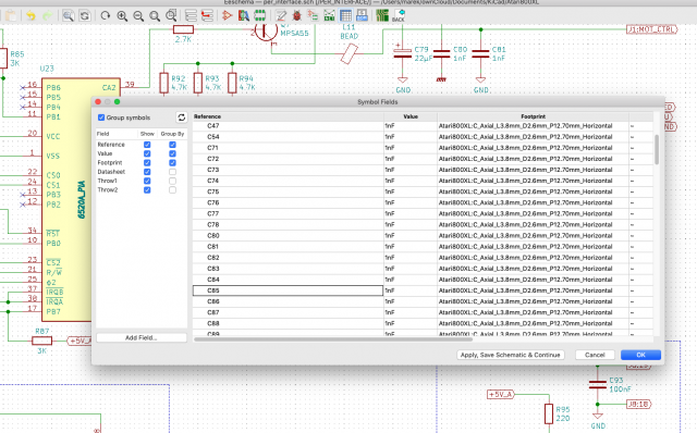
Bill of Materials (BOM) list of all the components needed can be exported from KiCad 5. With just the click of the Edit symbol fields icon ![]() inside Eeschema the entire BOM list will be shown. You can now press Ctrl + A or (Cmd + A on a Mac) and copy the whole table into a spreadsheet. I have tested it with Google spreadsheets and Excel and they both work. You can also use BOM plugins inside KiCad, but this involves more effort to setup. This is the complete BOM for this Atari 800XL project in CSV format as exported from KiCad.
inside Eeschema the entire BOM list will be shown. You can now press Ctrl + A or (Cmd + A on a Mac) and copy the whole table into a spreadsheet. I have tested it with Google spreadsheets and Excel and they both work. You can also use BOM plugins inside KiCad, but this involves more effort to setup. This is the complete BOM for this Atari 800XL project in CSV format as exported from KiCad.
It is possible to desolder all the parts from existing Atari 800XL PCB and solder them back onto the new board, but it is of course more fun to get them all new. Some of the components are proprietary to Atari and are not manufactured anymore, so you will need to make bigger effort to acquire them. In my case I have used an existing Atari 800XL and Atari 2600 Junior to get these parts. I haven't tried this, but I have read that it is still possible to order them at Best Electronics website. In my case I was building a PAL version of the system.
The custom Atari parts that are needed:
| Ref. on PCB | Part name | Atari code |
| U3 | XL / XE Memory Management Unit | CO61618 |
| U4 | XL Basic "B" | CO60302A |
| U5 | XL / XE OS | CO61598 |
| U7 | PAL XL / XE ANTIC | CO21698 |
| U8 | 6502C microprocessor called SALLY | CO14806 |
| U17 | PAL GTIA | CO14889 |
| U22 | POKEY | CO12294 |
| U23 | PIA 6520 | CO14795 |
| U29 | DELAY LINE | CO60472 |
| Y1 | 3.546894 MHz Crystal | CO16112 |
I have not tested it, but it seems that it might be possible to use W65C21 chip instead of the PIA 6520, which is more common and still in production. Also note NOT to use standard 6502 processor as the Atari version has an extra HALT pin, which is not known for the common 6502 processor.
As of Y1 crystal, I have desoldered it from Atari 2600 Junior PAL model (see picture below). You can basically also desolder Y2 and use it as well, but these are still being manufactured, so it is your choice. The reason that I have used Atari 2600 for this, is because I didn't want to touch my existing Atari 800XL board.
I have ordered less common parts like the power switch, crystal oscillator, 8SIP resistor networks, axial ceramic and electrolytic capacitors from DigiKey. Below is a list of the parts that I have ordered there.
| Ref. on PCB | Part name | Amt. | DigiKey code |
| Y2 | Crystal 4.433618 Mhz | 1 | X083-ND |
| RN1-RN4 | Res array 4 res 470 Ohm 8SIP | 4 | 4608X-2-471LF-ND |
| S1 | ROCKER switch SPDT 5A 120V | 1 | CKN2011-ND |
| C1 | 470μF - 16V - radial | 1 | 338-1678-ND |
| C2, C3, C10, C79 | 22μF - 16V - axial | 4 | 493-16599-ND |
| C19, C20, C22 | 4.7µF - 35V - unpolarized - radial | 3 | 493-12725-1-ND |
| C49 | 47µF - 16V - axial | 1 | 1572-1249-1-ND |
| C24, C50, C98 | 10µF - 16V - radial | 3 | 493-12763-1-ND |
| C17, C23, C63-C66 | Ceramic - 47nF - 50V - axial | 6 | 399-4476-1-ND |
| C59 | Ceramic - 22pF - 100V - axial | 1 | 399-4461-1-ND |
| C45 | Ceramic - 220pF - 100V - axial | 1 | 399-4462-1-ND |
| C52, C55 | Ceramic - 100pF - 50V - axial | 2 | 399-15255-1-ND |
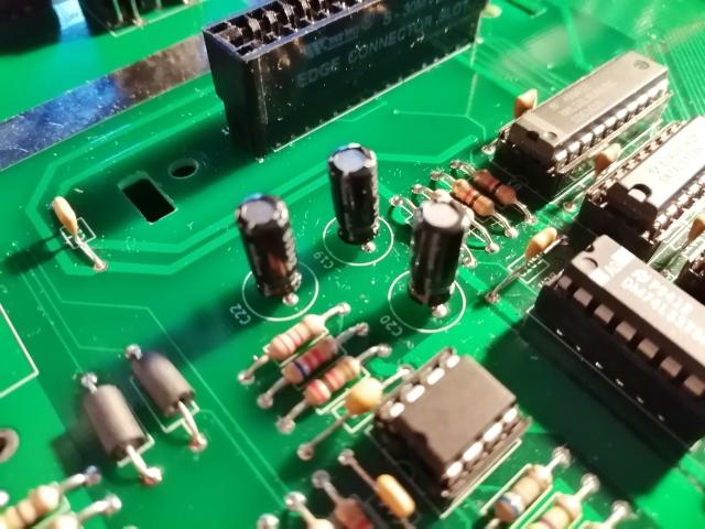
I could not find the correct size for the 4.7µF unpolarised capacitor though (see picture below), so they are a bit smaller than the original dimensions, which should be: Height: 11 mm, diameter: 8mm, lead spacing: 3.5 mm.
I did not order all the parts at DigiKey as I found them rather pricey and I also had to pay import taxes, so I started to look for other parts on Chinese online shops. Afterwards, it was not completely a wise choice to order all the remaining components there, as some of the parts did not arrive and others where of poor quality. Below I am listing the parts that were OK to be ordered in these Chinese online shops.
DIN7 power connector (J7). This connector should have footprint as shown below. I think that this is fairly standard spacing for this connector.
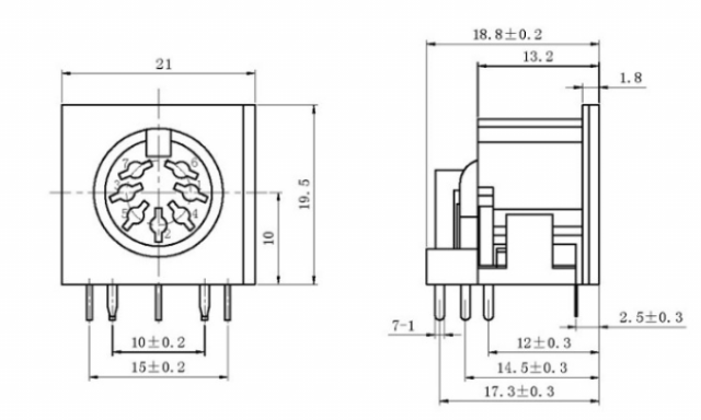
DIN5 monitor connector (J2). This is the footprint that is implemented on the PCB.
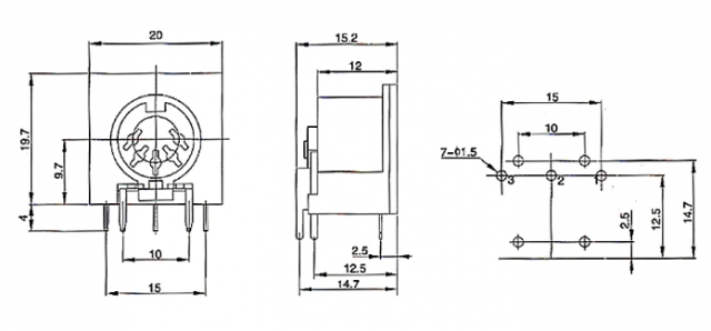
Ferrite beads (L1-L3, L7, L9, L11, L12). You will need 7 ferrite beads. There are no specs of what they should be, but I have ordered these ones with dimensions 6x3.5x0.8 and the finished Atari board was working just fine.
40-pin edge card connector (J4). This is for the cartridge slot.
4164 - 15ns DRAM chips (U9-U16). 8 pieces. They are compatible with the 4264 found on the Atari board and work as well.
Multi layer ceramic capacitors assortment (MLCC). Various between 5 pF - 820 pF. The reason that I have ordered them there and not at reichelt.de is because at reichelt.de they only have the ugly disc capacitors for picofarad (and 1 nF) values.
From this order I have used:
| Ref. on PCB | Capacitor value | Amt. |
| C44 | 68pF - 50V | 1 |
| C45 | 220pF - 50V | 1 |
| C52, C55 | 100pF - 50V | 2 |
| C59 | 22pF - 50V | 1 |
| C60 | 56pF - 50V | 1 |
| C111 | 820pF - 50 | 1 |
Inductors
This is the list of inductors needed on the board.
| Ref. on PCB | Inductor value | Amt. |
| L8 | 1.5µH | 1 |
| L19-L30 | 10 µH (0307) | 12 |
| L10, L15-L18 | 10 µH (0410) | 5 |
| L14 | 22 µH (0410) | 1 |
| L6 | 100 µH (0410) | 1 |
| L4, L5 | 820µH (0410) | 2 |
74LS51 (U30). This is an IC that I could not find on reichelt.de or conrad.nl/de. I have also ordered the other 74LS chips on a Chinese online web shop, but as I also ordered them at reichelt.de, they will be listed below.
What I also got on an online Chinese web shop, and I do not recommend getting there, are the THT resistors. They have thin wires and the colour codings looked very ugly.
I also found out later that some of the parts on other Chinese web shop are just as expensive as at reichelt.de and they get delivered to the Netherlands by DHL. So I have placed my next order for the components there.
It is also worth noting that axial ceramic capacitors are very hard to find and as an alternative I have used Multi-layer ceramic caps (MLCC). They are not axial, but found that it is quite easy to make them look almost axial.
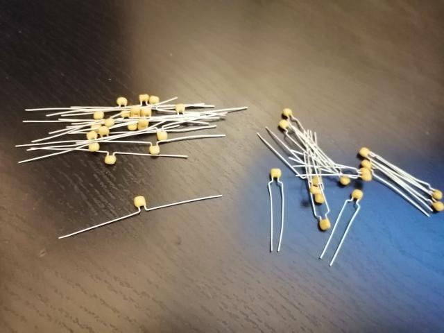
This is the list of the items ordered at reichelt.de:
| Ref. on PCB | Part name | Amt | Part number |
| C53 | MLCC - 3.9 pF | 1 | KERKO 3,9P |
| C7, C11, C94, C95 | MLCC - 10nF | 4 | Z5U-2,5 10N |
| C4, C13, C16, C18, C25-C32, C34-C43, C48, C51, C58, C61, C62, C68-C70, C93, C105-C109 | MLCC - 100 nF - 50V | 36 | Z5U-2,5 100N |
| CR1-CR5 | 1N4148 diode | 5 | 1N 4148 |
| Q1-Q6 | 2N3904 transistor | 6 | 2N 3904 |
| Q7 | MPSA56 transistor (replacement from MPSA55) | 1 | MPSA 56 |
| Q8, Q9 | 2N3906 | 2 | 2N 3906 |
| R1, R11, R59 | 2.2K | 3 | 1/4W 2,2K |
| R2, R7, R52 | 2K | 3 | 1/4W 2,0K |
| R3, R58 | 6.2K | 2 | 1/4W 6,2K |
| R4, R39 | 56K | 2 | 1/4W 56K |
| R5 | 470K | 1 | 1/4W 470K |
| R6 | 68K | 1 | 1/4W 68K |
| R8 | 5.1K | 1 | 1/4W 5,1K |
| R9, R62 | 3.3K | 2 | 1/4W 3,3K |
| R10, R13, R14, R37, R41-R45, R60, R61, R72, R80, R97 | 1K | 14 | 1/4W 1,0K |
| R35 | 33K | 1 | 1/4W 33K |
| R36 | 680 | 1 | 1/4W 680 |
| R38 | 500K | 1 | 1/4W 500K |
| R46 | 1.6K | 1 | 1/4W 1,6K |
| R47 | 36K | 1 | 1/4W 36K |
| R48 | 18K | 1 | 1/4W 18K |
| R49 | 9.1K | 1 | 1/4W 9,1K |
| R50, R63, R73, R81-R84, R92-R94 | 4.7K | 10 | 1/4W 4,7K |
| R51 | 750 | 1 | 1/4W 750 |
| R40, R53, R66, R90, R109, R112, R117, R119, R128-R131 | 100 | 12 | 1/4W 100 |
| R54 | 1.2K | 1 | 1/4W 1,2K |
| R55, R56, R67 | 75 | 3 | 1/4W 75 |
| R23-R30, R64, R70 | 10K | 10 | 1/4W 10K |
| R65 | 240 | 1 | 1/4W 75240 |
| R12, R15, R16, R19-R22, R31-R34, R68, R74, R75, R85-R88, R106 | 3K | 19 | 1/4W 3,0K |
| R69 | 6.8K | 1 | 1/4W 6,8K |
| R71, R113, R134-R137 | 470 | 6 | 1/4W 470 |
| R76-R79 | 1.8K | 4 | 1/4W 1,8K |
| R89, R96 | 47K | 2 | 1/4W 47K |
| R91 | 2.7K | 1 | 1/4W 2,7K |
| R98-R105, R107, R108 | 33 | 10 | 1/4W 33K |
| R95, R110, R118, R120-R127, R132, R133 | 220 | 13 | 1/4W 220 |
| R111 | 27 | 1 | 1/4W 27 |
| R114 | 1.5K | 1 | 1/4W 1,5K |
| R116 | 51 | 1 | 1/4W 51 |
| R140-R147 | 100 | 8 | 1/4W 100 |
| W1 | 0 Ohm | 1 | METALL 0,00 |
| U1 | LM358 | 1 | LM 358 DIP |
| U2 | 74LS138 | 1 | LS 138 |
| U18 | 74LS08 | 1 | LS 08 |
| U19 | 74LS14 | 1 | LS 14 |
| U20 | 4050 | 1 | MOS 4050 |
| U21 | 74LS74 | 1 | LS 74 |
| U24,U25 | CD4051BE | 2 | MOS 4051 |
| U26,U27 | 74LS158 | 2 | LS 158 |
| U28 | 74LS375 | 1 | LS 375 |
Orders at Conrad.nl/de
However, this was not the end of my orders. I already had a lot of components in stock, but there were still some missing. There was this special flat cable connector for the keyboard (J8). The only place that sells them is conrad.nl/de and it is called there: Connfly socket housing board 24 poles pitch: 2.54 mm DS1020-24ST1D. Conrad item number: 1390040.
The other capacitor value that I could not find was the Multi-layer ceramic capacitor in value of 1nF (Reference on board is: C5, C6, C8, C9, C12, C14, C15, C21, C46, C47, C54, C71-C78, C80-C92, C96, C97, C102, C110, C112), 37 pieces in total. These cound be found on conrad.nl/de. Conrad item number: 1578727
Joytick ports
The last item that were missing where the plastic DB9 joystick Atari ports (J5, J6). Part number CO19062. They can be salvaged from Atari 2600 Junior as well, but somebody has told me that these ports can also be found at retro-store.de. So I have bought them there.
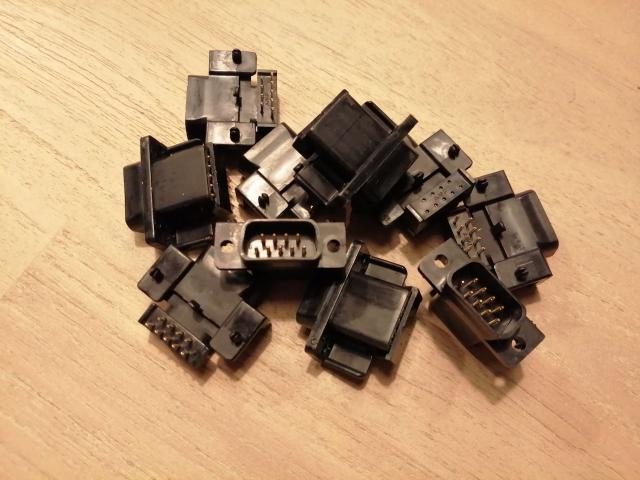
There are 2 other components, that I haven't mentioned. They are the RF-modulator and the SIO port. The RF-modulator is not really needed, unless you want to display the output of your Atari through the RF signal. As a replacement you could install Sophia video board, which will give you DVI output. But modding the Atari is a whole separate subject, which for sure I will dive in to at some point.
As for the SIO port, I could not find a replacement for it. For testing purposes I have soldered in some wires to the board and connected to SIO cable. I am currently working on version of the SIO port which can be 3D printed.
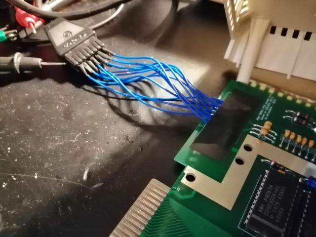
I totally forgot to mention that you will need IC-sockets. In total you will need 24 pieces in these dimensions:
| Ref. on board | Number of pins and size | Amt. |
| U1 | 8-pins (row spacing: 7.62mm) | 1 |
| U18, U19, U21, U29, U30 | 14-pins (row spacing: 7.62mm) | 5 |
| U2, U9-U16, U20, U24-U28 | 16-pins (row spacing: 7.62mm) | 15 |
| U3 | 20-pins (row spacing: 7.62mm) | 1 |
| U4 | 24-pins (row spacing: 15.24mm) | 1 |
| U5 | 28-pins (row spacing: 15.24mm) | 1 |
| U7, U8, U17, U22, U23 | 40-pins (row spacing: 15.24mm) | 5 |
Gathering of all these components took me the total of 2 month, but that is also because of the orders on Chinese webs shops and holiday season.
In the next blog post I will be describing the soldering process and also the troubleshooting of the PCB.

