The 6 mm aluminum frame cutout can now be mounted on the base of our frame. We could leave it as is, but adding the extra 10 mm threaded rod supports will give it that extra stability. The extra rods will also give us place to mount other additions to the printer.
We will need the following parts to complete the frame support. The printed parts that we are using are inside the Prusa mednel i3 Rework package and the Z-axis support parts (as mentioned in part 1 of this blog series).
- Printed parts Z-AXIS-TOP-LEFT-V2 and Z-AXIS-TOP-RIGHT-V2
- Printed parts 2x Z-axis_support_top
- 4x M3 x 25 mm (can be up to 30 mm) screws
- 4x M3 nuts
- 2x M3 washers
- 2x M10 x 350 mm threaded rods
- 16x M10 nuts and washers

The printed Z-AXIS-TOP parts will be used to hold the 8 mm smooth rod for the Z-axis. I have noticed that the printed hole is a bit tight and needs to be widen up a bit. I have used 8 mm wood drill bit and just turned it a couple of times with hand inside the hole.

Now attach the parts like in the picture below on the top of the 6 mm aluminum frame cutout. Don't forget the add the washers between the nut and the plastic part. BTW. They function as pressure dividers of the nuts and will give less stress to the plastic.

Now attach the M10 threaded rods to the top like this.

As I stared the project, it was only with a single bowden extruder, and after some upgrades I have ended up with a dual extrusion system. I give you the option, to add that extra extruder. I will assume you wish to do so, as the focus of this blog series is to build a 3D printer with dual bowden extrusion system. You have the possibility to create a bowden extruder yourself or save yourself a bit of trouble and buy one. I have chosen to buy 2 pieces of a metal bowden extruder. I have ordered one left and one right-handed. You will also need to print these mounts from this another Tech2C project. After you finish up you can add the extruders with the attached stepper motors to the M10 support bars on both sides. You will need to rotate the extruder 90 CW as the picture is not correct.

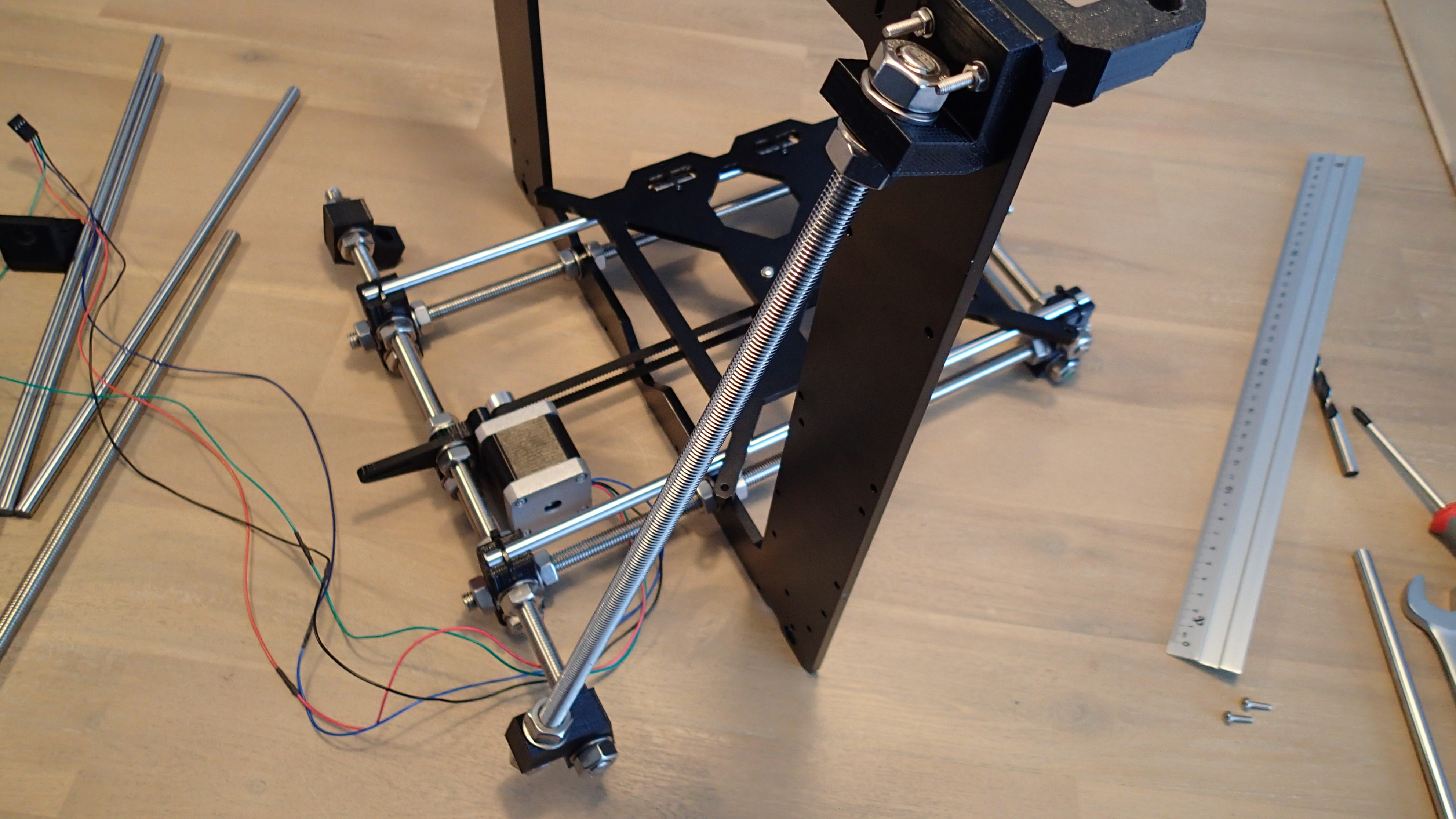
The bottom part of the Z-axis-support will look like this.

Another nice addition which is not in the pictures is the Compact Spool Holder with Bearing Support. This part is also mounted on the M10 support rod. So keep in mind that you will have that possibility when you start to tighten up the nuts.
In part 4 of this project we will finish up the Z-axis system.