There are a few simple assembly steps required to dress up your DE10-Nano board and transform it to a fully functional retro machine.
Make sure you have followed steps that are described here to install MiSTer software on your SD card.
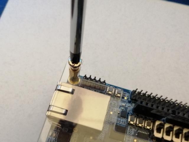
First step in the installation of the MiSTer IO Board is to detach DE10-nano plexiglass plate.
Now you can proceed with the attachment of the heat sink. First remove the 3M protection from the back of the 20mm heat sink and then place it precisely on the Altera Cyclone V SoC chip. Even if you don't have the MiSTer IO board, it is a good practice to do this.
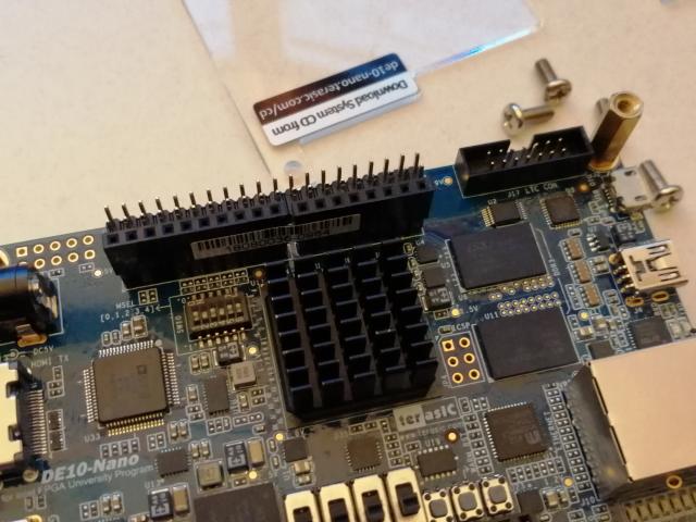
If you have the SDRAM module you can choose to install it now (it is also possible to install it after the MiSTer IO board is placed).
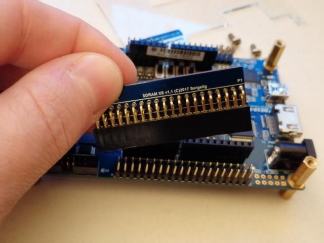
Note that there are pins on the back of the SDRAM module. These need to fit inside the header pin connector just like on the picture below.
Best way to insert the card is to support the back of the DE10-Nano board and push it gently inside
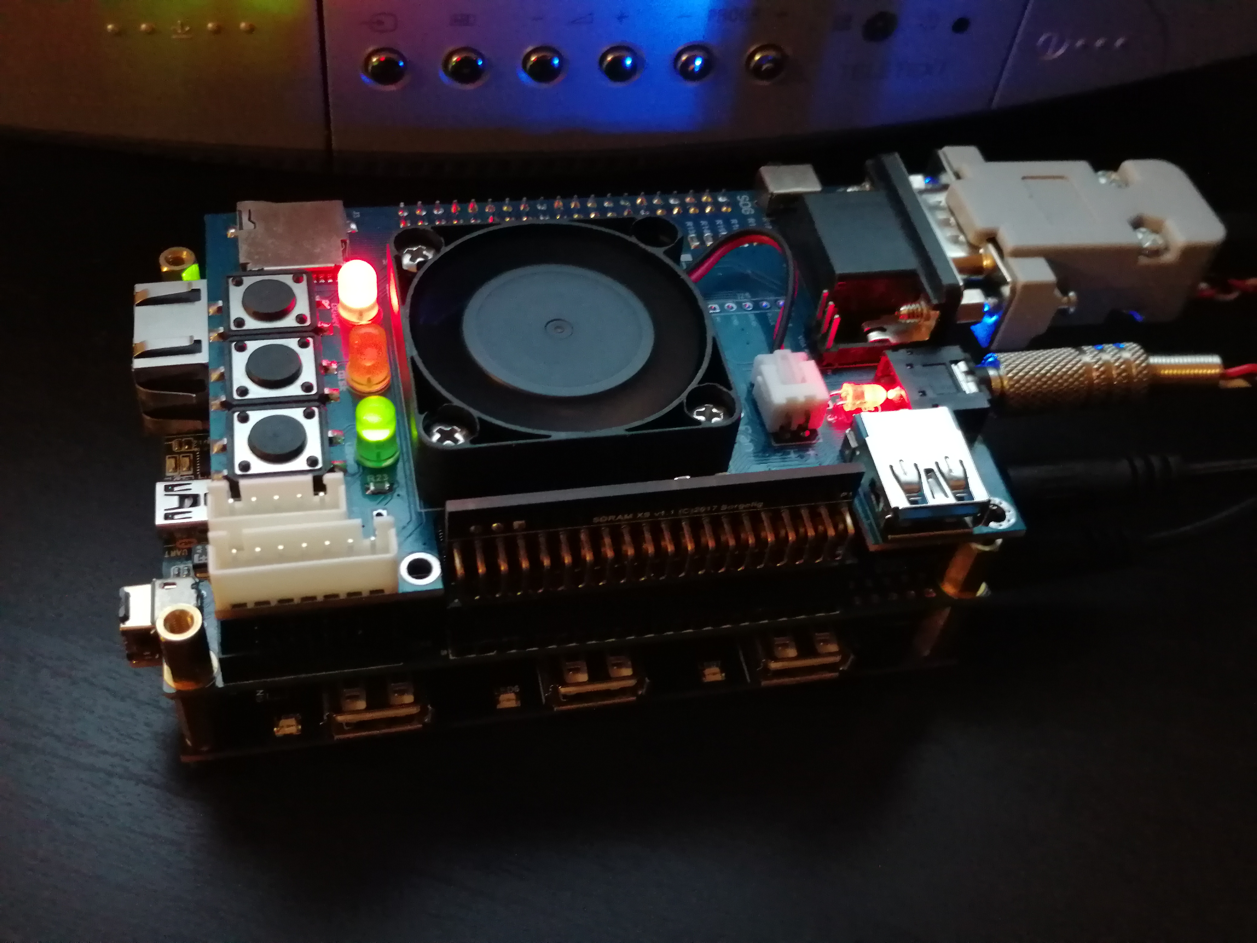
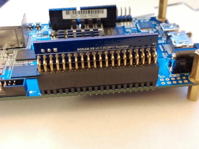
It should end up looking like this
NOTE: If you want to install the MiSTer USB Hub, you need to unscrew the spacer screws with the coupling long hex nuts and reverse them so the long side will be on the bottom. As it will become clear later in this tutorial, you can then attach the USB Hub board on the bottom of the DE10-Nano board.
![]()
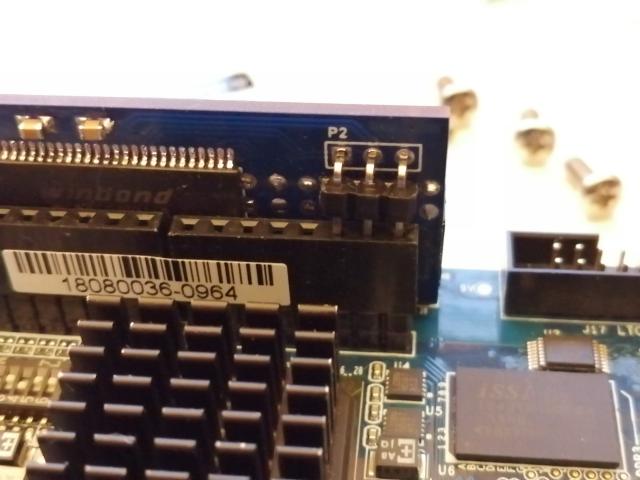
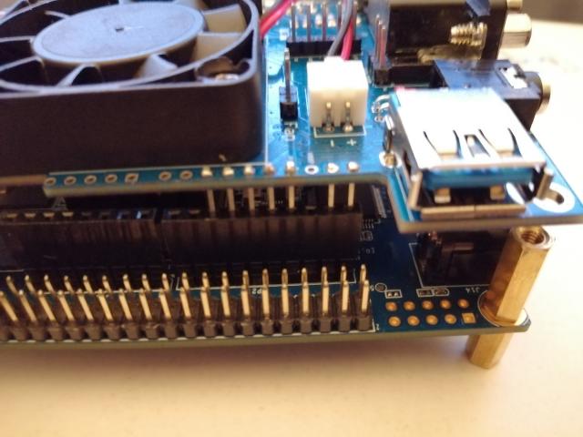
On the bottom of the IO Board, next to the 2 row pin header note all the pins. Including the pin P9 as shown in the picture below.

In the next pictures I have removed the SDRAM module, for better visibility on how to insert the IO board, but you can easily leave it attached. Insert the board horizontally, so pins on both sides will be inserted simultaneously. To see that you are inserting on the correct side check that the heat sink is blow the fan and the screw holes are aligned.
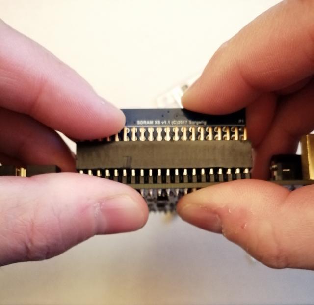
Picture below shows the side of the SDRAM module.
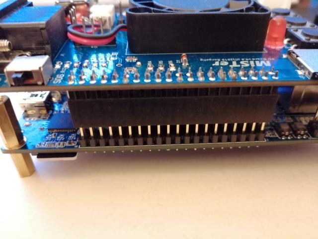
And the opposite side (where the 2 row header is attached to the IO board). Then push it gently in place.
If you don't have the MiSTer USB Hub v2.1 (and did not reverse the spacer screws) you can now tighten 2 of the screws to the MiSTer IO Board.
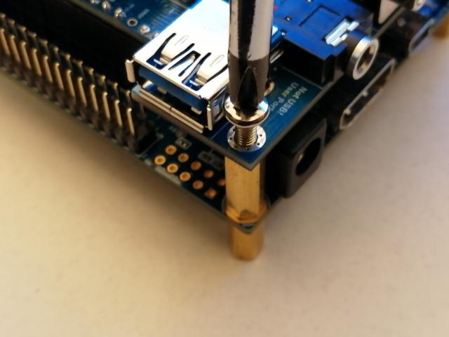
The last step is to attache the MiSTer USB Hub v2.1 with USB Bridge. First make sure you have the spacer screws reversed, so the longer side is on the bottom of the DE10-Nano board.
![]()
Start by inserting the USB Bridge on the USB Hub board.
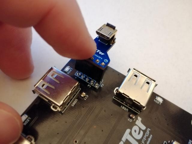
Shown from another angle you can see it is facing the inside of the USB Hub board.
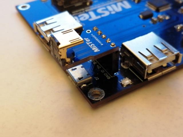
Now you can put the DE10-Nano with the IO Board on top of the USB Hub and slide it in a way that the Micro USB connector of the DE10-Nano will connect to the USB Bridge.
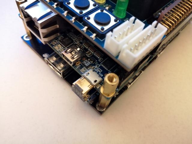
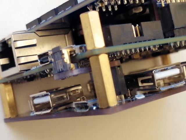
USB Hub and bridge shown from an alternate angle.
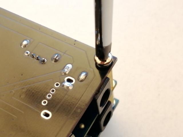
Finish with attaching the screws on the bottom of the USB Hub. The MiSTer IO Board does not have any screws installed, but the header pins are holding it firmly are are not really needed. You can always buy 2 pieces of slightly longer spacer screws or use some M3 washers and tighten it with a M3x10 screw when you are in doubt. I will leave it up to you.
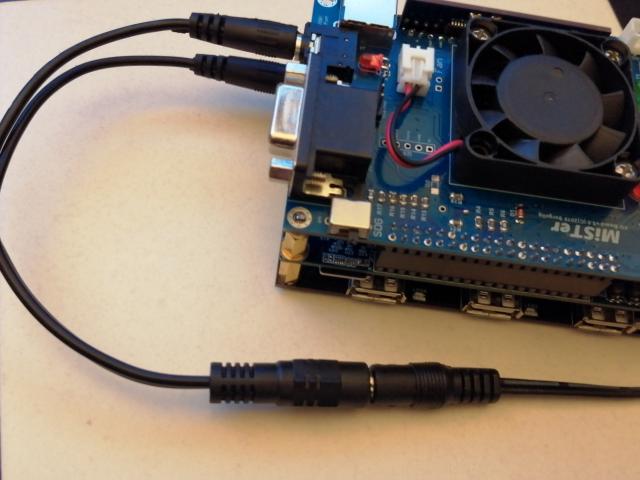
When you buy the USB Hub in my Tindie store, I also provide this power splitter cable with the board that you can use to power the DE10-Nano and USB Hub with the same power adapter.