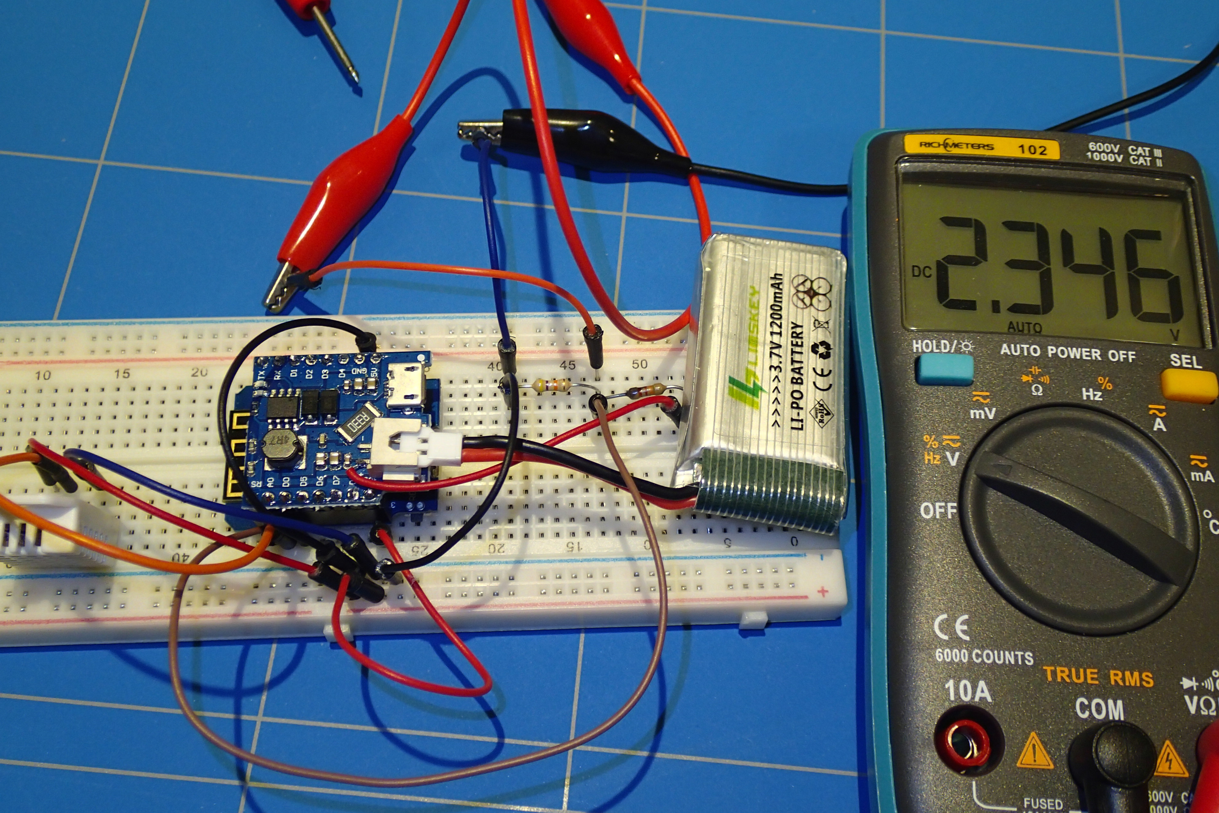
In addition to the WeMos battery powered temperature server, it would be nice to know what the remaining level of the battery is, so we can recharge it in time. This is easily done using a voltage divider circuit and the analog input on the WeMos D1 mini module.
The analog input of the WeMos module can measure voltages between 0 and 3.3V. The values that can be read out are between 0 and 1023. Our Li-Po battery is 4.2 or even sometimes 4.5 volts on full charge so if we would directly connect it to the analog port it would destroy the ESP chip on the board. So we need to create a voltage divider circuit to drop the voltage that is send to that input to the maximum of 3.3V. We also need to keep in mind that the voltage divider itself also consumes battery power and we need to draw as little current as possible.
The voltage divider circuit needs 2 resistors connected in series.
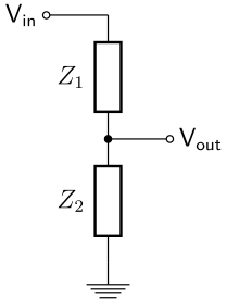
The output Vout is calculated using this formula:
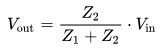
So we need to choose our values that 4.2V will output 3.3V. The ratio is more or less 3/4 between the output and the input. The resistance of Z1 needs te be smaller than Z2; 75% smaller. The other consideration is the power consumption as we know P = V * I, the less current we draw the less power of the battery we will consume. The formula to calculate the current through a voltage divider is:
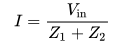
The conclusion is that the bigger the resistance of Z1 and Z2 is, the less current we will draw. The impedance of the analog pin A0 is very high and draws around 10 µA (microAmpere) of current, so we can ignore it in our calculations. Another consideration is more of a practical nature and that is the readily available resistor values. For Z2, I have chosen a resistor value of 47K and if we calculate Z1, based on that value it should be 17K, however the usual resistor assortment does not include this value. The closest we can get is 22K. When we use these values, Vout of our voltage divider will be around 3V. That is close enough.
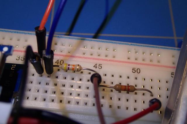
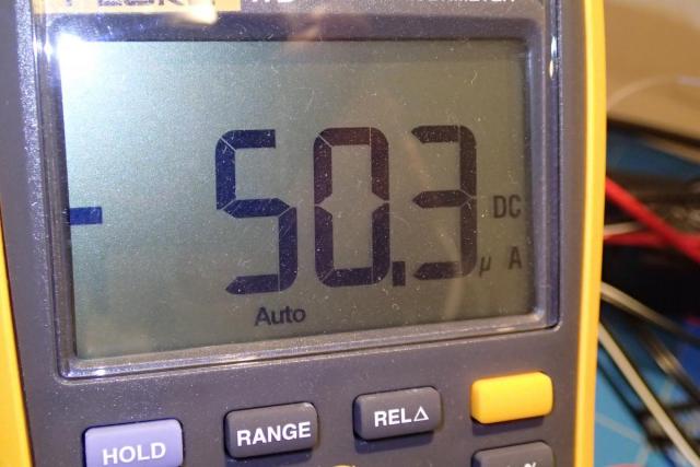
The current that we will draw (without the analog pin as load) at a fully charged battery (4.2V) will also be as low as 4.2 / 69000 = 60 µA. After building this circuit and measuring it, it was actually 50 µA, due to fabrication errors of resistors and the voltage drop across the analog pin A0.
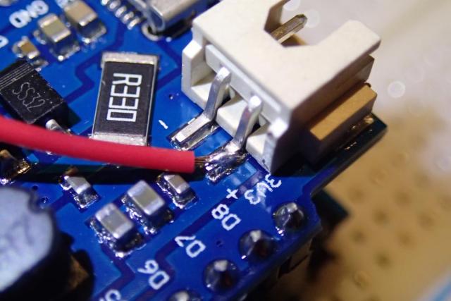
We also need to solder an extra wire to the positive output of the battery on the battery shield. This wire is out Vin in the voltage divider circuit. Vout goes to the analog pin A0 on the WeMos board.
It is now time to add some code inside our sketch.
Inside the handeRoot() function (from our last project) add this line:
int nVoltageRaw = analogRead(A0);
float fVoltage = (float)nVoltageRaw * 0.00486;
And change the output of our server to:
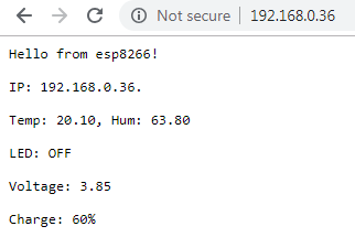
server.send(200, "text/plain", "Hello from esp8266!\n\rIP: " + ip_str + ".\n\rTemp: " + strTemp + ", Hum: " + strHum + "\n\r" + strLedPin + "\n\r" + "Voltage: " + fVoltage);
This way we will be able to see the voltage of our battery. I calculated the value of 0.00486 by dividing the voltage across the resistors with the analog output nVoltageRaw. The charging curve is more or less linear, so it should give correct voltage. It might be different in your case. From the voltage we can derive the charge of our Li-Po battery. This is the table of reference:
| Voltage (V) | Charge (%) |
| 4.2 | 100 |
| 4.15 | 95 |
| 4.11 | 90 |
| 4.08 | 85 |
| 4.02 | 80 |
| 3.98 | 75 |
| 3.95 | 70 |
| 3.91 | 65 |
| 3.87 | 60 |
| 3.85 | 55 |
| 3.84 | 50 |
| 3.82 | 45 |
| 3.80 | 40 |
| 3.79 | 35 |
| 3.77 | 30 |
| 3.75 | 25 |
| 3.73 | 20 |
| 3.71 | 15 |
| 3.69 | 10 |
| 3.61 | 5 |
| 3.27 | 0 |
We can add extra code to show the charge derived from this table:
float fVoltageMatrix[22][2] = {
  {4.2,  100},
  {4.15, 95},
  {4.11, 90},
  {4.08, 85},
  {4.02, 80},
  {3.98, 75},
  {3.95, 70},
  {3.91, 65},
  {3.87, 60},
  {3.85, 55},
  {3.84, 50},
  {3.82, 45},
  {3.80, 40},
  {3.79, 35},
  {3.77, 30},
  {3.75, 25},
  {3.73, 20},
  {3.71, 15},
  {3.69, 10},
  {3.61, 5},
  {3.27, 0},
  {0, 0}
};

int i, perc;

perc = 100;

for(i=20; i>=0; i--) {
  if(fVoltageMatrix[i][0] >= fVoltage) {
    perc = fVoltageMatrix[i + 1][1];
    break;
  }
}
Then change the server output line to:
server.send(200, "text/plain", "Hello from esp8266!\n\rIP: " + ip_str +
  ".\n\rTemp: " + strTemp +
  ", Hum: " + strHum +
  "\n\r" + strLedPin +
  "\n\r" + "Voltage: " + fVoltage +
  "\n\r" + "Charge: " + perc + '%');
Now we will be able to see the charge of the batter alongside the voltage.
You can download here the complete sketch.