WeMos D1 mini is an ESP8266 based board that can be programmed with Arduino IDE. In this blog I will describe how to make a simple WiFi based server that is being powered by a Li-Po battery and shows temperature and humidity inside your browser window.
A while back I have ordered this board together with a couple of battery shields and a Li-Po battery.
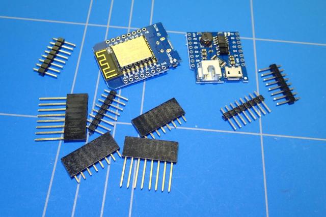
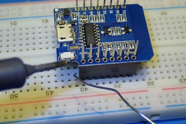
They came packed with multiple pin headers, and that was handy as you could use them to stack the battery shield on top of the WeMos board. The pins needed to be soldered and I have used a breadboard to hold the pin headers in place. I have selected the ones with long pins so I would also have the option to stick the board on a breadboard.
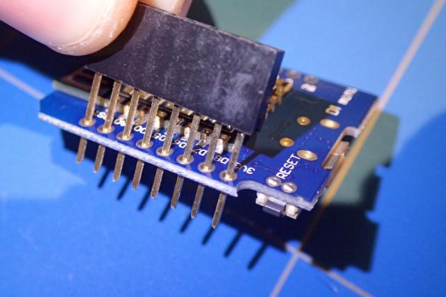
The headers could now be soldered, keeping in mind the orientation of the pins so they could be correctly stacked on top of each other.
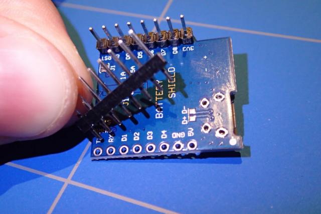
I did the same with the battery shield.
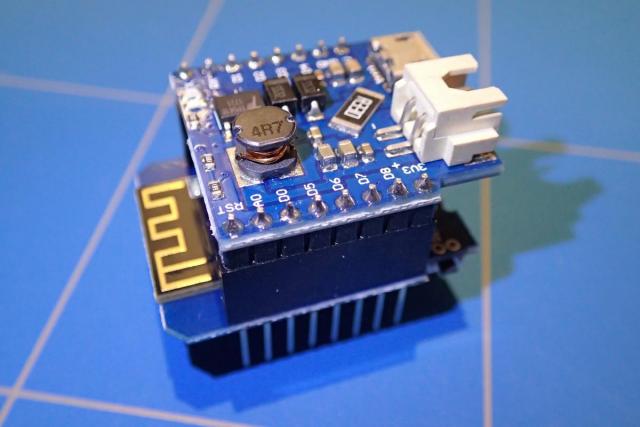
After stacking the battery shield on top of the WeMos board, it looked like this:
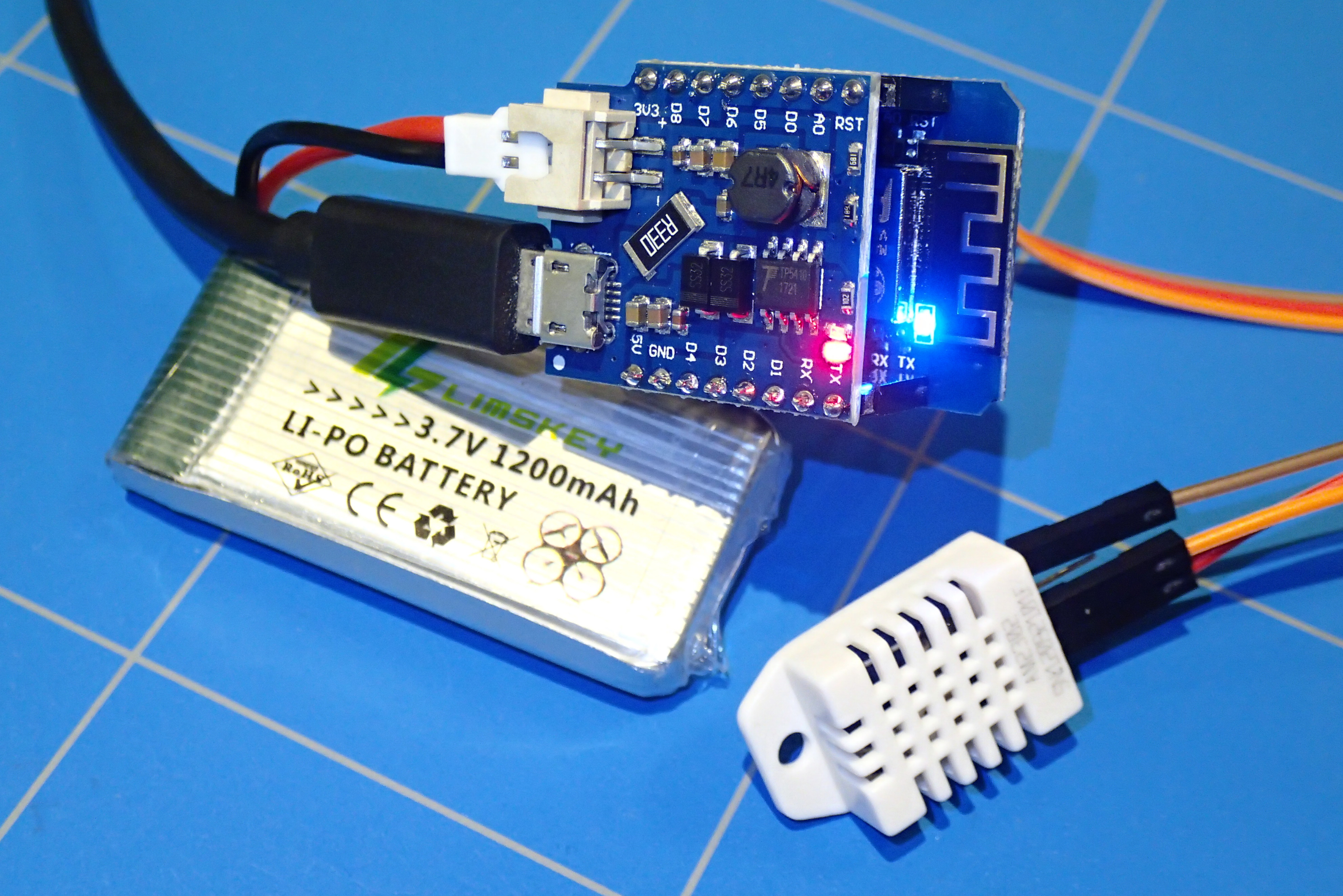
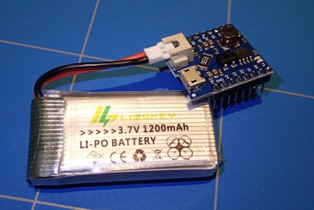
It was time to connect and test the battery. I have used a Limskey 3.7 1200mAh Li-Po battery. The connector on my battery was not a absolute fit, but I managed to connect it. You really need to be very careful here and watch the polarity of the battery! The battery shield have no protection if you connect it in the wrong way. The first time I made this mistake and just saw smoke coming out of my battery shield.
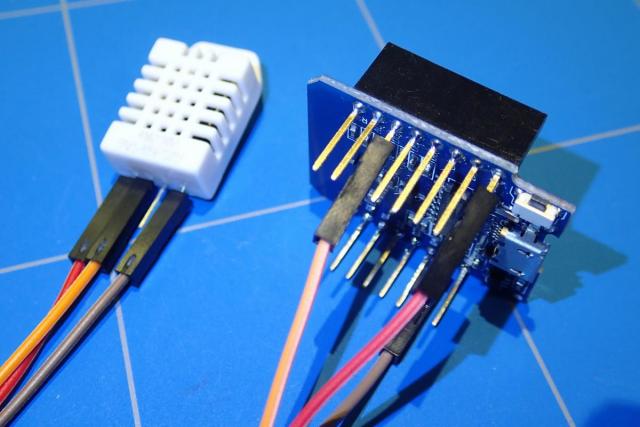
To finish the hardware part of our project we will connect the DHT22 temperature / humidity sensor to our board. In comparison to DHT11, the resolution of the DHT22 is better. It can measure temperatures in steps of 0.1 °C. Connect the 3.3V pin on the WeMos board with the VCC pin of the DHT22 (left most pin when viewing the front of the sensor and red wire on the picture). Then connect ground pins together. (Brown wire on the picture). The last pin is the data pin (orange in the picture). Connect it to D0 on the WeMos board. One of the pins of the DHT22 is not connected (NC).
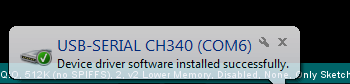
In the previous blog we have seen how to program an ESP-01 board. The WeMos D1 Mini is basically more of the same. The only exception is that you don't need an external FTDI interface as the module already has an USB to Serial chip onboard and that is the CH340. You will also need drivers for it. Download the CH340 drivers here. After installing the driver and connecting the board with USB you should get a message mentioning the COM port. In my case I was using Windows 7.
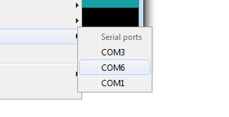
Now you can choose your newly added COM port inside the Arduino IDE (menu Tools -> Port -> COM6)
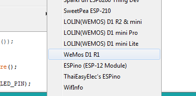
Assuming you already followed the steps to add ESP8266 library to your Arduino IDE (if not then follow the instructions given here), you can select the correct board, which is WeMos D1 R1.
Now inside the menu item Sketch -> Include Libaray ... -> Manage Libraries ... we are going to add required libaries for our ESP8266 WiFi Server and DHT22 temperature sensor. They are:
- DHT sensor library for ESPx - For DHT22 temperature and humidity sensor
- Page builder (by Hiereomon Ikasamo) - For ESP8266WebServer support
Now we will be able to write our sketch and use these libraries in the code.
To start let's add those libraries to the top of the file:
#include <ESP8266WiFi.h>
#include <WiFiClient.h>
#include <ESP8266WebServer.h>
#include "DHTesp.h"
However it is not mandatory to use defines, they can help you if you quickly want to change the assignments to your pins. For the DHT22 we will be using D0 pin on the WeMos board, and the pin number is 16.
#define DHT_PIN 16
Below you can see a list of all the pins that are available on the WeMos board for assignments inside the Ardino IDE. Some of the pins have multiple functions and have internal pull-up or pull-down resistors (those can be handy when using buttons). D4 pin is also connected to the blue LED on the board.
| WeMos Pin | Function | Arduino IDE |
| A0 | Analog input, max 3.3V input | A0 |
| D0 | IO | 16 |
| D1 | IO, SCL | 5 |
| D2 | IO, SDA | 4 |
| D3 | IO, 10k Pull-up | 0 |
| D4 | IO, 10k Pull-up, BUILTIN_LED | 2 |
| D5 | IO, SCK | 14 |
| D6 | IO, MISO | 12 |
| D7 | IO, MOSI | 13 |
| D8 | IO, 10k Pull-down, SS | 15 |
Remaining pins on the WeMos board are:
| WeMos Pin | Function |
| G | Ground |
| 3.3V | 3.3V |
| 5V | USB voltage |
| TX | TX Data |
| RD | RD Data |
| RST | Reset |
The ESP8266 chip will connect to your WiFi router and it needs to know your SSID name and the password.
//SSID and Password of your WiFi router
const char* ssid = "yourwifi_ssid";
const char* password = "your_password";
We will be running our server on HTTP port, which is port 80.
ESP8266WebServer server(80); //Server on port 80
Finally we need to create a global variable for our DHT sensor that we can use in various functions.
DHTesp dht;
The fist function that is called after you turn on your WeMos (or any other Arduino based module) is the setup() function. All initialisations go here. Start by defining this function like this.
void setup(void) {
}
Inside this function we will add some initial things that must be done before the board will actually do something. For debugging purpuses it is handy to use serial monitor. Serial monitor can be started inside the Tools menu. As a parameter of this function the speed of your serial connetion is given.
Serial.begin(115200);
ESP8266 can function is Access Point mode. This means that the WiFi SSID will be visible when you list all available networks in your neighbourhood. If you wish to disable this feature then add this line to the setup function:
WiFi.mode(WIFI_STA);
Then we can connect to our WiFi router with:
WiFi.begin(ssid, password);
This function will print a empty line inside the serial monitor window:
Serial.println("");
Here we are checking if the WiFi connection is already established. Every 500 ms (0,5 second) a dot is printed inside the serial monitor. When the ESP8266 is not able to connect to your router, it will try to do it infinitely.
while (WiFi.status() != WL_CONNECTED) {
  delay(500);
  Serial.print(".");
}
After a successful connection we can print some handy things inside the serial monitor. Like the IP address that your router assigned to it.
//If connection successful show IP address in serial monitor
Serial.println("");
Serial.print("Connected to ");
Serial.println(ssid);
Serial.print("IP address: ");
Serial.println(WiFi.localIP());
To handle HTTP request we need to add the line before. The handleRoot function will be executed when someone will view the IP address of the ESP8266 inside a browser.
server.on("/", handleRoot);
The function below will start out server and print a status message inside the serial monitor.
server.begin();
Serial.println("HTTP server started");
We will use the built-in LED to check if the temperature is above a given level. WeMos board must know that this LED is actually an output pin.
pinMode(LED_BUILTIN, OUTPUT);
Finally we will define which sensor we are using. In our case it is DHT22
dht.setup(DHT_PIN, DHTesp::DHT22)
The second function that needs to exist in every Arduino IDE sketch is the loop() function. As the name suggests it executes indefinitely (until you turn off the device of course). Inside this function we will handle the HTTP request and enable / disable the built-in LED if the temperature rises / falls below 25 °C.
void loop(void){
  server.handleClient();

  float temperature = dht.getTemperature();

  if (temperature > 25) {
    digitalWrite(LED_BUILTIN, LOW);
  }
  else {
    digitalWrite(LED_BUILTIN, HIGH);
  }
}
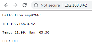
The handle function that we specified inside the setup() will need to be defined. This function will show the temperature and humidity when you open the IP of your ESP8266 chip inside the browser. According to the temperature if will also print the tekst LED: ON or LED: OFF. This page is rendered as content type text/plain ,but you can ofcourse make it nicer and output it with real HTML. If you want to do that you will need to change it to text/html.
void handleRoot() {
  IPAddress ip_address = WiFi.localIP();
  String ip_str = IpAddress2String(ip_address);

  float humidity = dht.getHumidity();
  float temperature = dht.getTemperature();

  bool stateLedPin = digitalRead(LED_BUILTIN);

  String strLedPin = stateLedPin ? "LED: OFF" : "LED: ON";

  String strTemp, strHum;
  char tmp[10];
  char hum[10];

  dtostrf(temperature, 1, 2, tmp);
  strTemp = tmp;
  dtostrf(humidity, 1, 2, hum);
  strHum = hum;

  server.send(200, "text/plain", "Hello from esp8266!\n\rIP: " + ip_str + ".\n\rTemp: " + strTemp + ", Hum: " + strHum + "\n\r" + strLedPin);
}
The final function is to convert the IP address (from an IPAddress struct) to a string object. Otherwise we will not be able to print the IP address inside the browser window:
String IpAddress2String(const IPAddress& ipAddress)
{
  return String(ipAddress[0]) + String(".") +\
  String(ipAddress[1]) + String(".") +\
  String(ipAddress[2]) + String(".") +\
  String(ipAddress[3])  ;
}
We are finished creating our sketch. Now we can compile it and upload it to our board. When you press the Upload icon ![]() it shall do both.
it shall do both.
Don't forget to change the SSID and password for your WiFi router.
Below is the source code of the whole sketch. You can also download here the zipped INO project.
#include <ESP8266WiFi.h>
#include <WiFiClient.h>
#include <ESP8266WebServer.h>
#include "DHTesp.h"

#define DHT_PIN       16

//SSID and Password of your WiFi router
const char* ssid = "yourwifi_ssid";
const char* password = "your_password";

ESP8266WebServer server(80); //Server on port 80
DHTesp dht;

/***************************************************************
* SETUP
**************************************************************/
void setup(void){
  Serial.begin(115200);
  WiFi.mode(WIFI_STA);

  WiFi.begin(ssid, password);     //Connect to your WiFi router
  Serial.println("");

  // Wait for connection
  while (WiFi.status() != WL_CONNECTED) {
    delay(500);
    Serial.print(".");
  }

  //If connection successful show IP address in serial monitor
  Serial.println("");
  Serial.print("Connected to ");
  Serial.println(ssid);
  Serial.print("IP address: ");
  Serial.println(WiFi.localIP());  //IP address assigned to your ESP

  server.on("/", handleRoot);      //Which routine to handle at root location

  server.begin();                  //Start server
  Serial.println("HTTP server started");

  pinMode(LED_BUILTIN, OUTPUT);

  dht.setup(DHT_PIN, DHTesp::DHT22); // Connect DHT sensor to GPIO16
}
/***************************************************************
* LOOP
**************************************************************/
void loop(void){
  server.handleClient();          //Handle client requests

  float temperature = dht.getTemperature();

  if (temperature > 25) {
    digitalWrite(LED_BUILTIN, LOW);
  }
  else {
    digitalWrite(LED_BUILTIN, HIGH);
  }
}

/***************************************************************
* This function converts IPAddress struct to a String
**************************************************************/
String IpAddress2String(const IPAddress& ipAddress)
{
  return String(ipAddress[0]) + String(".") +\
  String(ipAddress[1]) + String(".") +\
  String(ipAddress[2]) + String(".") +\
  String(ipAddress[3])  ;
}

/***************************************************************
* This routine is executed when you open its IP in browser
**************************************************************/
void handleRoot() {
  IPAddress ip_address = WiFi.localIP();
  String ip_str = IpAddress2String(ip_address);

  float humidity = dht.getHumidity();
  float temperature = dht.getTemperature();

  bool stateLedPin = digitalRead(LED_BUILTIN);

  String strLedPin = stateLedPin ? "LED: OFF" : "LED: ON";

  String strTemp, strHum;
  char tmp[10];
  char hum[10];

  dtostrf(temperature,1,2,tmp);
  strTemp = tmp;
  dtostrf(humidity,1,2,hum);
  strHum = hum;

  server.send(200, "text/plain", "Hello from esp8266!\n\rIP: " + ip_str + ".\n\rTemp: " + strTemp + ", Hum: " + strHum + "\n\r" + strLedPin);
}
The code supports showing the IP with serial monitor, but if this does not work you can always go to your router and see which IP address it assigned. In my case it was local IP 192.168.0.42. It is easy to recognise as the name begins with ESP_

When you visit that IP address with your browser you should be able to see the temperature and humidity. If you get an error NaN (Not a Number), you have somewhere made a mistake. In my case it was the ground pin that was not connected correctly to the WeMos board.
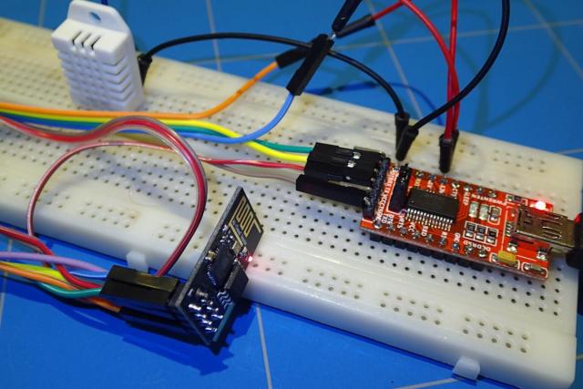
Btw. You can also run this project on any other EPS board. I created the initial setup of this project on an ESP-01 board. The only thing that needs to be changed is the definition of the DHT_PIN and the built-in LED pin and it should work without any problem.
#define DHT_PIN       2
#define BLUE_LED_PIN  1