The stepper motors must know when they have reached the limits of an axis. For this purpose we use endstops.
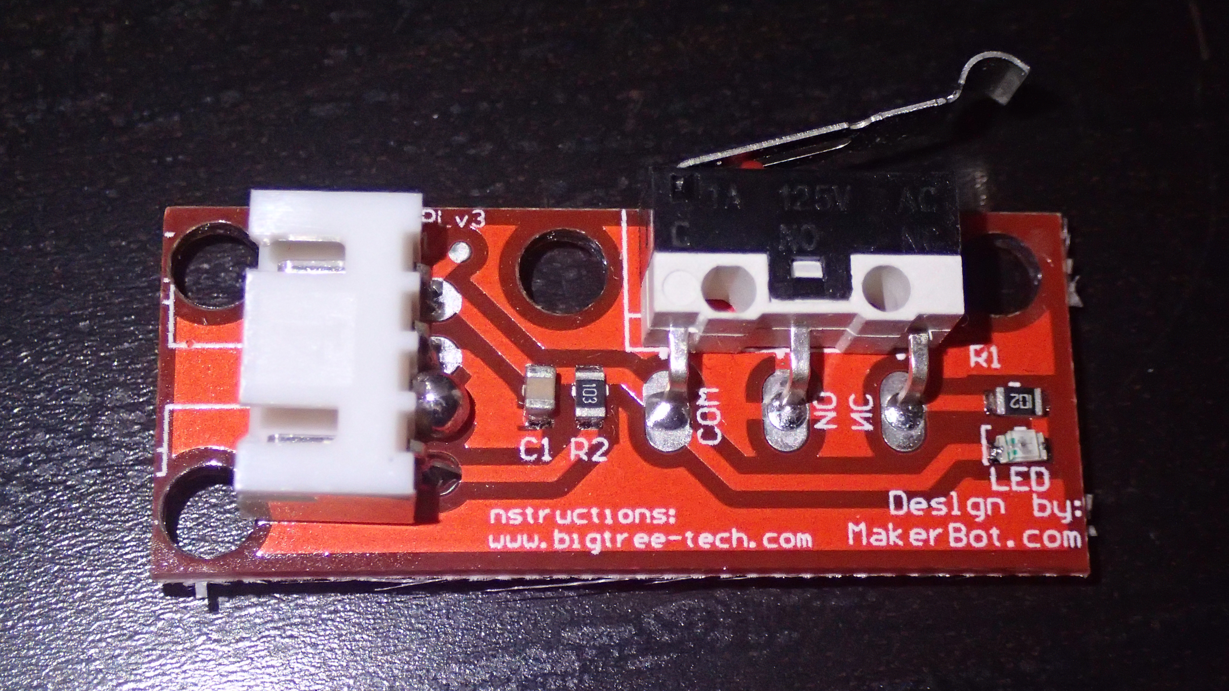
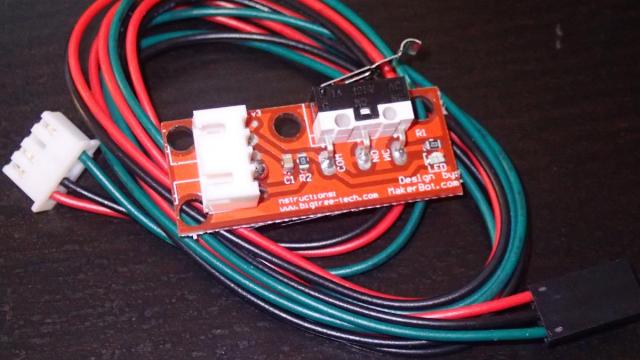
It theory it is actually possible to connect 6 endstops in a 3D printer. Two for each axis, but usually is it not needed as you only want to know when you have reached a zero point. Although it is possible to print outside the bounds, nobody minds it. An endstop is actually nothing else than a microswitch. Some companies have made nice PCB with controlling leds and connectors, but there is no immediate need fot that for the 3D printer. However, just to make things easier for yourself they are available. The endstops that I have used are designed by Makerbot and manufactured by Bigtree-Tech. The complete package includes the endstop and a cable to connect to the RAMPS 1.4 board.
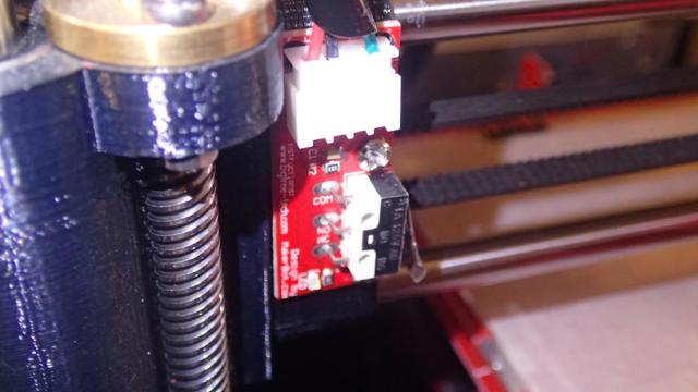
The PCB also provides holes so it is easy to mount them on the frame. As I mentioned before you need 3 of them. To start with we have the Y-axis endstop. It is connected to the back of the frame, on the part called Y-MOTOR. In part 1 of this blog you can read more about this printed part. Connect this endstop just like on the picture below with 2x M3 x 12 mm screws, nuts and washers. The bed platform must be able to press the switch when it is all the way to the back.
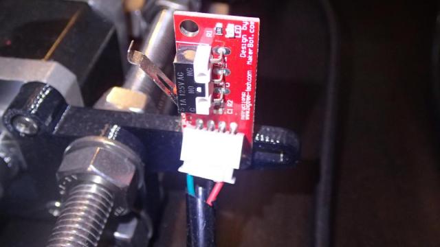
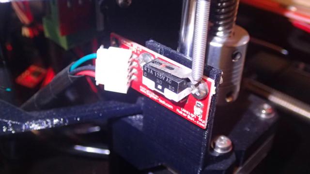
The next endstop that we will cover is the X-asis. Because the standard part provided in the Prusa i3 Rework collection is actually connected on the right side to the X-axis idler and we are not using it, we need to print an extra part. Download and print this X-axis endstop mount. It is actually from the P3steel project, but it will fit just fine on our Rework frame. Connect the endswitch PCB with 2x M3 x 12 mm screws to this part.
Now you can click it on the 8 mm X-axis bars and slide all the way to the left. The connector and cable will point to the top, which is actually a good thing. I guess it is also possible to place it on the right of the frame, and use it as max-endstop. Or even just like in the original Rework project a "negative" 0-endstop. It will all become clear as we will start to confiture the Marlin firmware. There are settings in the code where the position of the endstops can be configured.
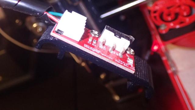
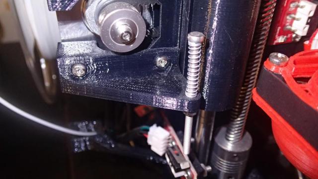
The last, and in my opinion the most fun endstop to make is the Z-axis endstop. There are countless possibilities and projects that solve the problem of this endstop. Among many they include optical, magnetic or even proximity sensors that will enable to find the zero position of your Z-axis. In our case we will use the same switch as for the other axes. One of the best projects that I could find was the Z endstop easy adjustment kit for Prusa mendel i3. It consists of two parts. One of the parts is attached to the Z-motor mount. This is also the place for the endstop switch. Mount it like on the picture below.
The other part of the endstop is placed on the X-axis stepper motor. It provides a hole for a M3 screw where you can make easy adjustments for where the Z stepper motor needs to stop rotating. Place a spring between the screw and the printed Z-endstop-moving part. I have actually used a spring from a pen. In my case the M3 screw was 50 mm in length. Do not forget to place a nut on the other side to hold the screw in place.
We have reached the point where we have installed all the mechanical parts in our 3D printer. In the next parts we will cover the heated print bed and electronics.