ESP8266 is Wi-Fi microchip which can be programmed just like a normal Arduino board. For that purpose some additional software needs to be installed inside the Arduino IDE.
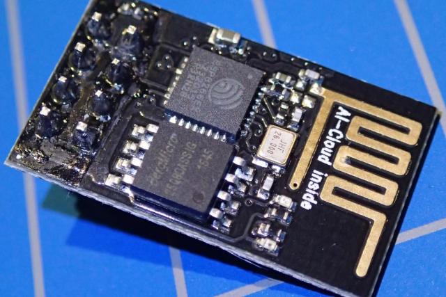
There are various versions of this module, but for this experiment I will be using the ESP-01 module, as it is actually the cheapest. It can be found for the price of around 1 euro.
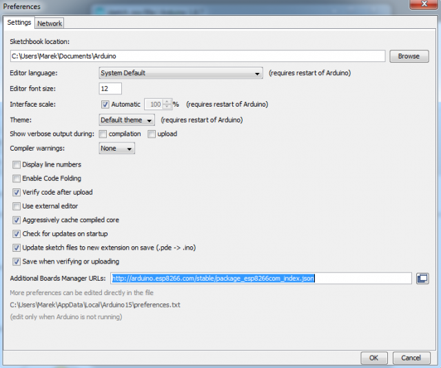
These steps describe the installation in Windows. To start we will download the latest version of the Arduino IDE software. During writing of this blog it is version 1.8.7. After you have installed the software go the the File -> Preferences menu item and paste the URL below into Additional Boards Manager URLs:
http://arduino.esp8266.com/stable/package_esp8266com_index.json
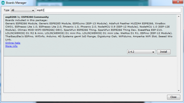
After clicking OK, your Arduino libraries should update. Go to the menu Tools -> Board: [some default board] -> Boards Manager.. menu and install esp8266 by ESP8266 Community. Simply start typing esp82 and this board should show up.
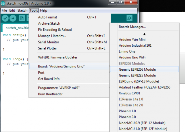
When you now go to the Tools -> Boards menu, a lot of ESP boards will be displayed. In our case we will select Generic ESP8266 Module.
Now it's time to connect the ESP-01 module to our programmer board. You will basically need a USB to serial adapter. I will use FTDI FT232R, which I have used before to program a STM32 micro-controller chip for the Amiga floppy disk drive emulator. Note that it needs to support 3.3V!
The pinout of ESP-01 module is as follows:
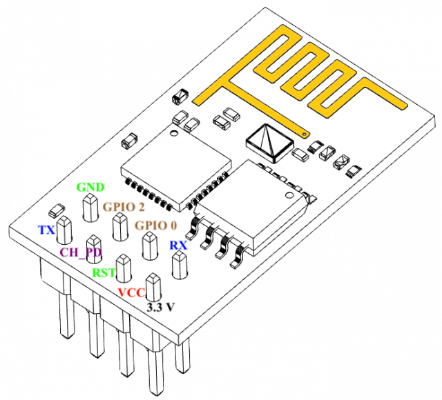
- VCC, Voltage (+3.3 V; can handle up to 3.6 V)
- GND, Ground (0 V)
- RX, Receive data bit X
- TX, Transmit data bit X
- CH_PD, Chip power-down
- RST, Reset
- GPIO 0, General-purpose input/output No. 0
- GPIO 2, General-purpose input/output No. 2
The connection that you need to set-up are: (Note that in order to put ESP-01 in programming mode the CH_PD needs to be connected to VCC and GPIO_0 to GND).
| ESP-01 Module | FTDI USB-serial interface |
| VCC (3.3V) | VCC (3.3V) |
| GND | GND |
| TX | RX |
| RX | TX |
| CH_PD | VCC |
| GPIO_0 | GND |
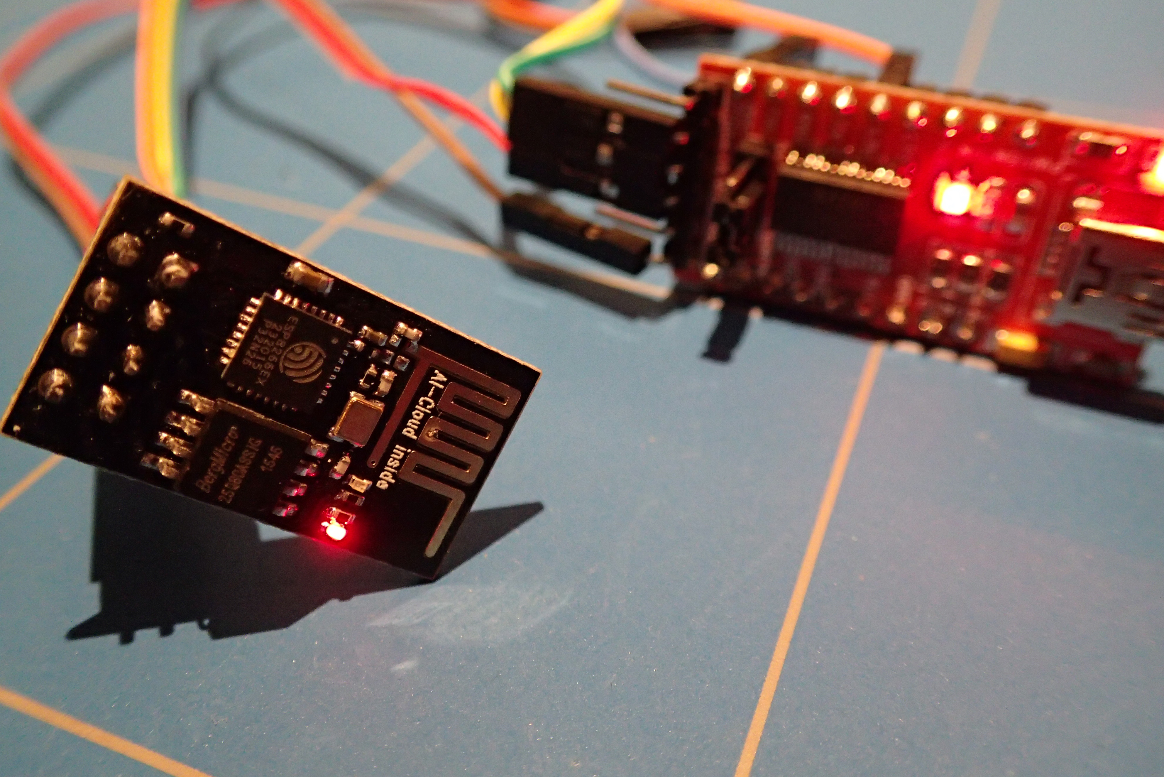
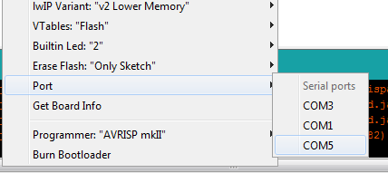
In order to select the correct COM port go to Tools -> Port menu inside the Arduino IDE and note which are listed. After you connect the USB cable to the computer and the red LEDs of both boards will lit up, go back to the same menu and select the extra COM that is listed. It is possible that you need to install correct FTDI drivers for Windows. I have found my drivers on this website.
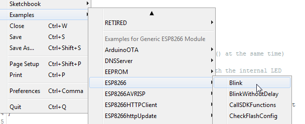
Inside the Arduino IDE go to File -> Examples -> ESP8266 and select the Blink sketch. You can now Upload it to your ESP-01 board. The blue LED should start blinking.
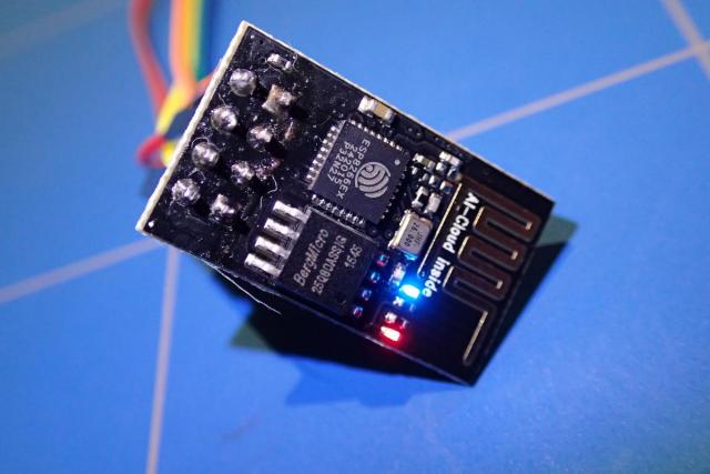
If the LED does not blink (like in my case) you need to change the output pin (LED_BUILTIN) inside the sketch to pin 1. In some boards it apparently differs. My final sketch looked like this
#define MY_BLUE_LED_PIN 1

void setup() {
  pinMode(MY_BLUE_LED_PIN, OUTPUT);     // Initialise the LED_BUILTIN pin as an output
}

// the loop function runs over and over again forever
void loop() {
  digitalWrite(MY_BLUE_LED_PIN, LOW);   // Turn the LED on (Note that LOW is the voltage level
  // but actually the LED is on; this is because
  // it is active low on the ESP-01)
  delay(1000);                      // Wait for a second
  digitalWrite(MY_BLUE_LED_PIN, HIGH);  // Turn the LED off by making the voltage HIGH
  delay(2000);                      // Wait for two seconds (to demonstrate the active low LED)
}
After uploading the sketch the led should start blinking right away. If not you can unplug the GPIO_0 connection from the FTDI programmer board and reconnect the USB.
If this still does not work you can reconnect the USB cable and load the default Blink sketch from the File -> Examples -> ESP8266 -> Blink menu:
Then inside the Tools menu change the Builtin Led setting to "1":

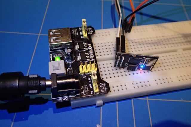
If you want to run the board on a standalone power source (3.3V) you need to make 3 connections. The 2 obvious are VCC, GND, but without connecting CH_PD pin to VCC, the board will not work. Below you can see a picture of such standalone connection using a 3.3V power source plugged into a breadboard.