If you ever owned a Commodore 64 and it broke down, there is a big chance that the failure was caused by the PLA chip.
As this chip is not manufactured anymore, people have created replacements for it.
A while back I also made a prototype for such a replacement using a CPLD chip and it worked, but I never did any further tests and completed the project.
I thought that it was time to do some more tests on the chip. But will it pass the tests? Let's find out...
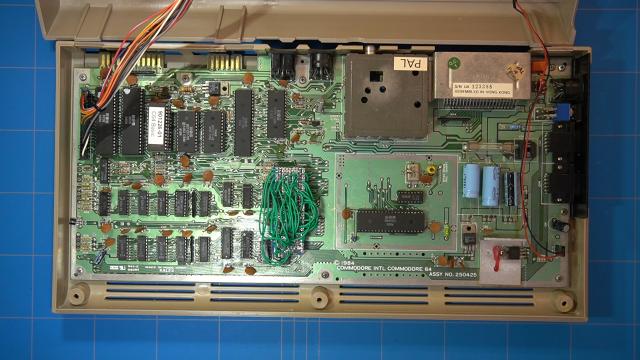
This was the Commodore 64 that was not working at the time. Next to a broken PLA chip, it also had a faulty BASIC and DRAM chip. I have created some blog posts in the past like this EPROM BASIC chip replacement, so feel free to read more about it.
However this blog will not be about repairing the C64, but instead I will zoom in on the PLA and explain a little bit about the operation. The details of how I created and programmed the CPLD chip you can also read on my blog.
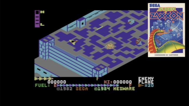
The question that had bugged my mind was if the chip would also work on the C64 Super Zaxxon cartridge. Unfortunately I was not in possession of one nor did I want to spend 200 dollars on purchasing one on eBay.
A solution came to me after watching a video where the creator of PLAnkton explained how to test a custom made.
Video explaining how to test PLA by Francois Leveille

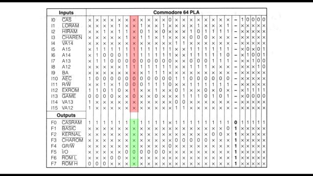
So what is a PLA chip and what does it do? Simply put it is a look-up-table that transforms inputs into outputs. This is also the reason that it can be implemented in a EPROM chip as you can use the address pins as inputs and data pins as outputs. So for example when the PLA chip receives these bits on its inputs, then on the output pin CASRAM will be brought HIGH and I/O pin will be pulled LOW.
So in the case of a faulty PLA or one with wrong timing, there could be collisions on the bus as multiple outputs can become active at the same time.
Taking a quick look at the VHDL code of the PLA, we can see that this logic can be easily implemented inside a CPLD or an FPGA chip. The highlighted rows in the code correspond to the example we mentioned earlier.
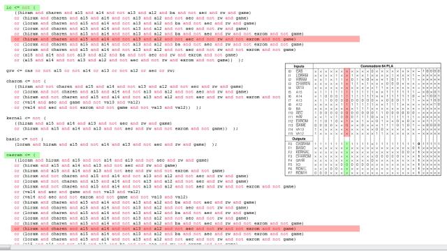
The complete VHDL code of this project and a more detailed explanation of my custom PLA, can be found here.
Let's take a look on how we will proceed with the test of the custom PLA chip.
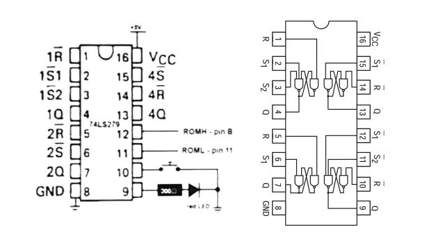
When we zoom in on the schematics of Francois Leveille, we can see that it uses an SR-Latch with 2 Set inputs. They are connected to ROM Low and ROM High pins on the cartridge port. The R (which is the Reset input) is connected to a switch. After boot, both of the pins are set low, and the Latch is put briefly in the SET state also the LED will indicate that, but after the reset switch is pressed, the Latch should never be set again. If that happens, then you have a faulty PLA.
In this schematic we see a 74LS279 chip, which already has multiple SR-Latches built in. In my case I did not have this chip at hand, but I did have a 74LS00 chip, which has 4 NAND gates and that is enough to build an SR-Latch with 2 SET inputs.
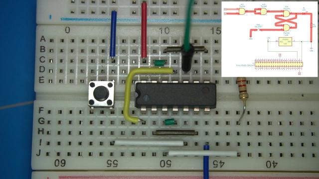
This is the schematics that I have come up with as I do not have a PCB of it yet I will build it on a breadboard.
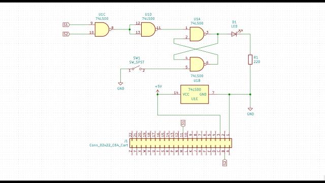
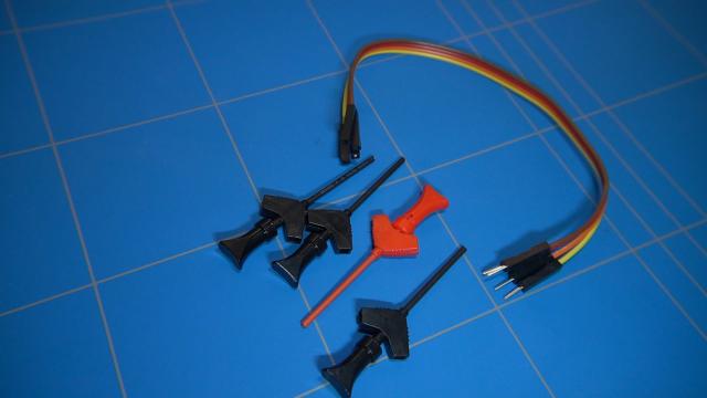
For this project we will need a NAND chip as I mentioned before, tactile switch, LED with 220 ohms resistor and some jumper wires.
I have also added this small prototyping board with the thought of using it to slide inside the cartridge port, but more on that mistake later.
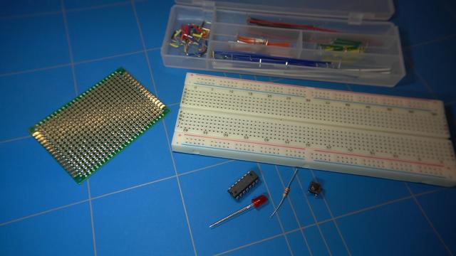
Let's start by populating the board with components. NAND gate chip, LED with resistor and the push switch for the re-set button.
The chip will need 5V of power and ground. We will tap the power in the later stage from the commodore cartridge port. For testing the circuit we will use a power supply.
Next we can make the connections from the schematics.
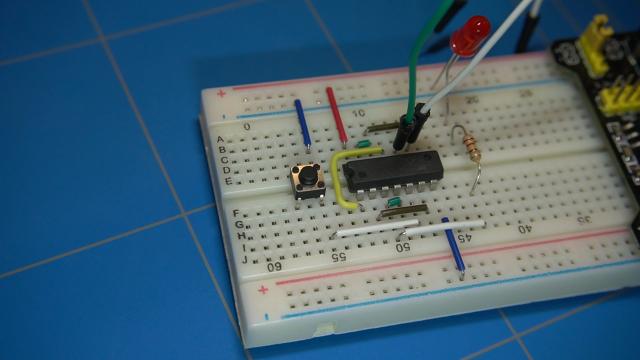
We are all set, so let's test the circuit.
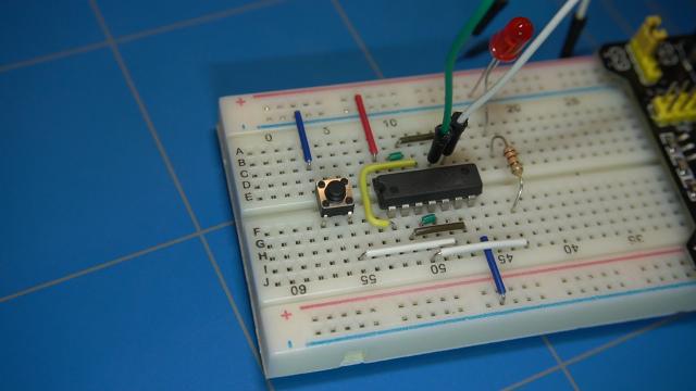
Wait a second. This is actually not right.. the led should stay on. What is wrong with it? None of the set inputs are working.
It took me a while to figure out what was wrong, I even swapped the NAND gate chip. The solution was actually simple. One of the wires that connects the input switch to ground was wired to the wrong pin. The circuit was actually resetting the whole time and the LED turned off immediately after disconnecting from the set input.
After testing it again, it's working as it should.
It's time to use the proto board and connect it to the commodore's cartridge port.
I would actually only need a couple of pins from the port and the board should be wide enough. But it does not fit, let's fix that and destroy this proto board, I mean... cut off a corner so it will fit.
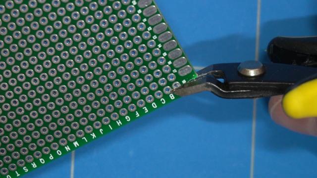
Little bit of filing should make it even better.
But wait a minute.. aren't the pads on the opposite sites connected to each other? As the matter of fact they are.. I have also measured it. This means that the proto board will be useless. The connectors on the cartridge port would make a short. Luckily I realized this mistake before sticking it into the commodore and possibly breaking it.
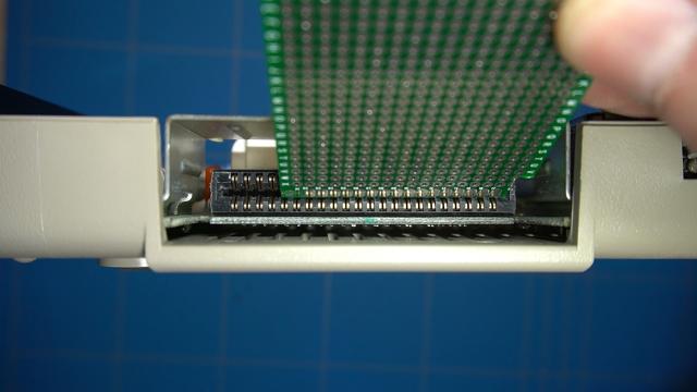
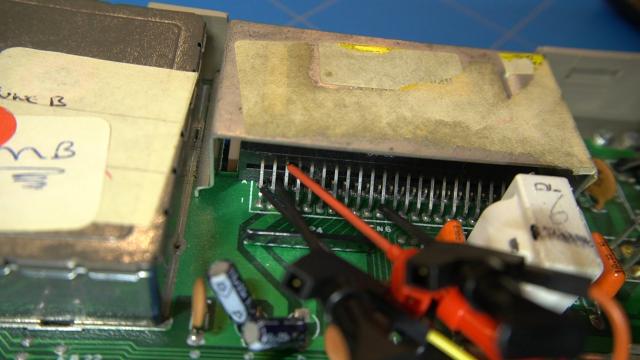
So as an alternative approach I will use these mini grabber IC hook test clips. At least I think that's how you call them. They will connect to the cartridge port, from the inside.
Continuing with the cartridge port.. first connect the ground and 5 volt wires. Pin and 1 and 3. Then we connect the other clips to pin 11 and pin B, which is on the second row. It is a bit hard to connect it this way.
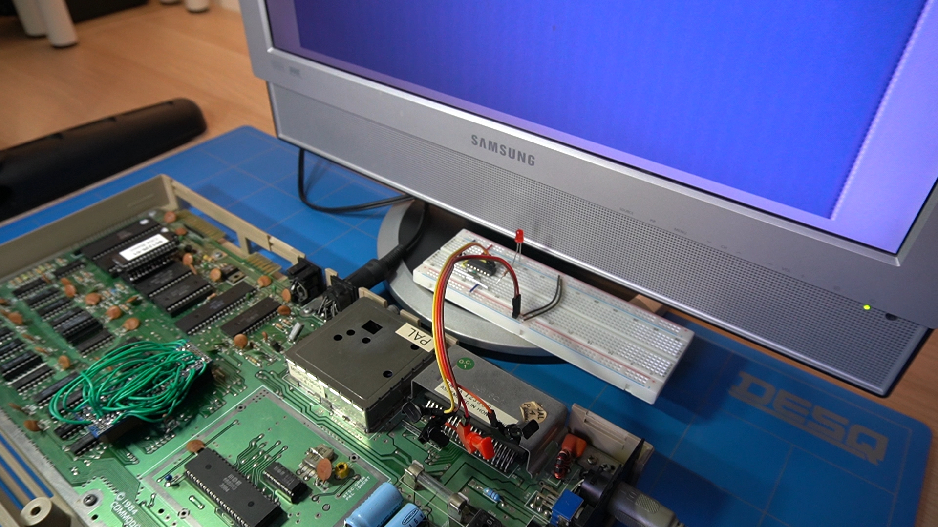
On the breadboard we connect power and ground from the cartridge port and also the wires to the 2 SET pins which will be triggered by the ROM High and ROM Low output pins of the PLA.
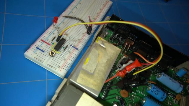
And finally the moment we have all been waiting for. We can test the PLA chip. Let's turn the computer on. The LED lights up, which is good.
Now I will reset the circuit and hope that the LED will not turn back on. And it's NOT, so that means it's a success! The PLA is working as it should!

Well this was just a small test and I am sure there are more aspects of the PLA that I did not touch. By the way, the revision of the board that my commodore computer had was 250425. I did not have another board to test it.
If you have any other ideas on how I should continue testing the PLA chip, please contact me.