An undertaken electronic project does not always need a dedicated Arduino board. Sometimes it is sufficient to use separate Atmel ATmega328P chip and add some parts around it to make it work.
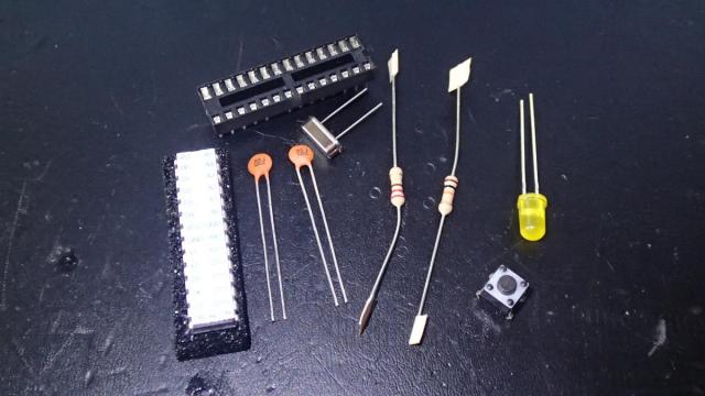
In this small project we are going to build a breadboard with the ATmega328P chip and program it using an Arduino Nano board. First we need to inventorize which parts are needed:
- Atmel ATmega328P chip
- 16 MHz crystal
- 220 ohm resistor
- 10K ohm resistor
- 5mm LED (Yellow)
- 2 x 22 pF capacitors (code 220)
- 28 pin IC socket (optional)
- 4-Pin Tactile Button Switch (for the reset button, also optional)
- Breadboard
- Arduino Nano
- 22 AWG wires. I only had black and red, but it is good practice to use another neutral color (like blue).
We can build the board according to this schematic that I have created in Cadsoft EAGLE. This program also allows you to create PCB layout from the schematic. In the future I will cover this in more detail. As have you probably noticed, I have added an ISP header, but on the breadboard we will just use direct wire connections to the ATmega chip.

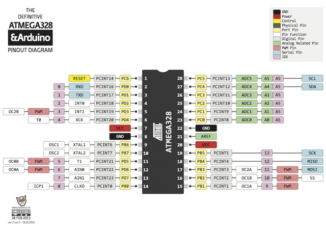
The LED is connected to pin 2 of the chip, which in the Arduino IDE is connected to digital pin number 0. I admit that it was a mistake in the design as I have actually connected the LED to pin 4 of the chip (PD2), which is arduino digital pin 2. PD0 is used for RXD serial communication, and although it is possible to use it, I did not test this scenario in this setup. In the schematic below you can see (pink label) how the chip is wired to the Arduino digital and analog pins.
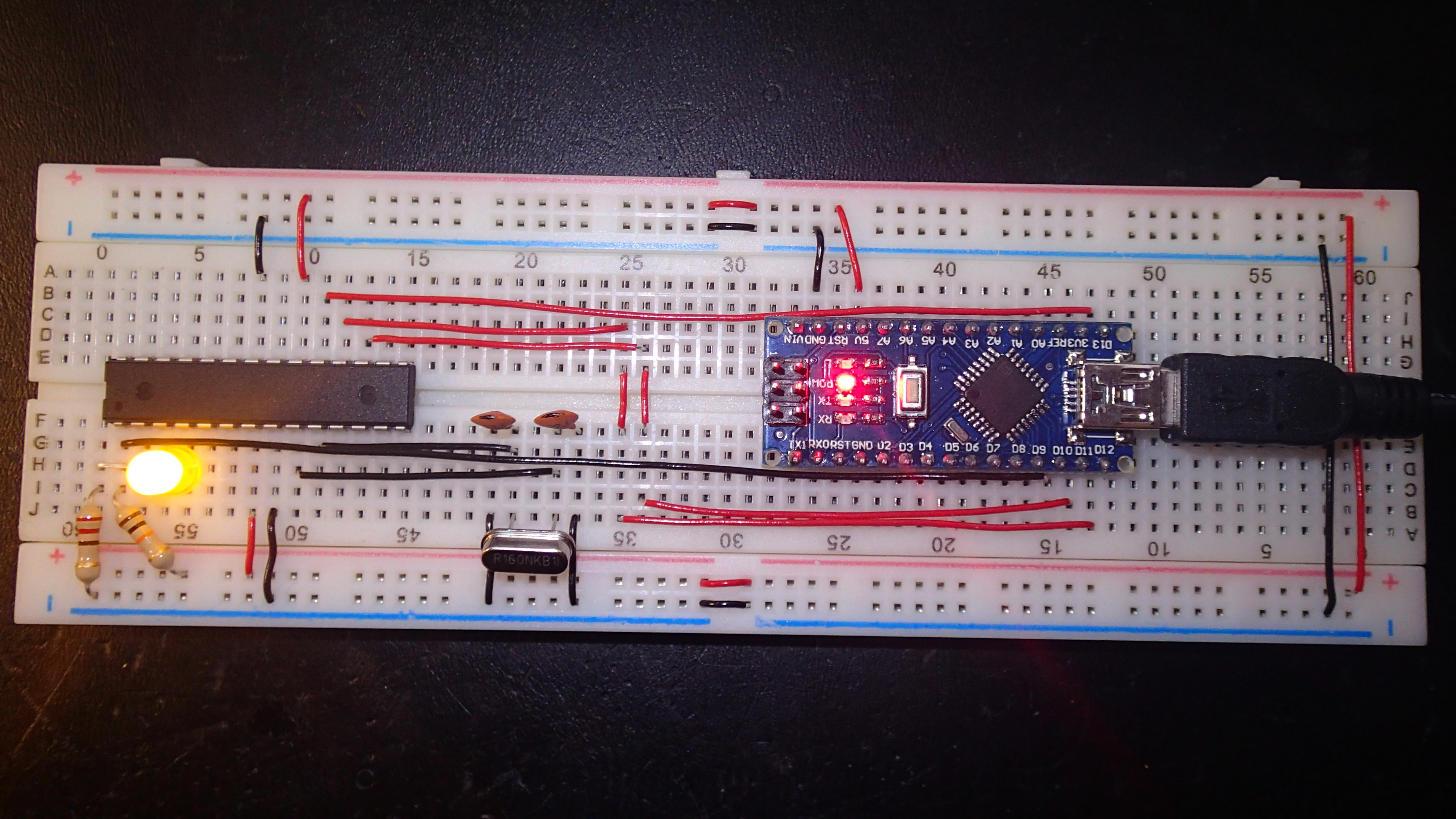
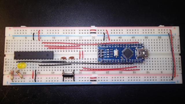
In the picture below you can see how the connections are made to the Arduino Nano board. We will use it as Arduino ISP programmer. Notice that the ISP header pins from the schematic are connected according to the list below to the Arduino Nano:
- Arduino Nano D13 to ATmega328P pin 19 (SCK)
- Arduino Nano D12 to ATmega328P pin 18 (MISO)
- Arduino Nano D11 to ATmega328P pin 17 (MOSI)
- Arduino Nano D10 to ATmega328P pin 1 (RESET)
- Arduino Nano 5V to 5V line on the breadboard
- Arduino Nano GND to GND line on the breadboard
The power will be supplied by USB and it provides enough current for both the Arduino Nano and the Atmel chip.
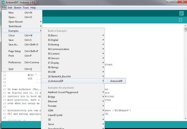
After you are done building the breadboard it is time to program the Atmel chip with the Arduino using the IDE. To start you need to program the Arduino Nano with the ArduinoISP Sketch. You can find it in File -> Examples -> 11. ArduinoISO -> ArduinoISP.
Now select the Arduino Nano as normal and upload this sketch as you would do with a normal project.
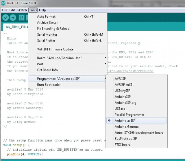
Now in the Tools menu select the Programmer: Arduino as ISP
At this point you might need to burn bootloader. My ATmega chip was already provided with the bootloader, but you might want to do this step before proceeding with programming of the ATmega chip. The taget board needs to be set to Arduino Nano and ATmega328p, but because we are already using a Nano board, this should be already set. To write the bootloader select Tools -> Burn Bootloader.
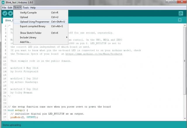
Now you are ready to program the Atmel chip. From File -> Examples select Basics and Blink sketch and change the pin number that you have used in the breadboard connection. Now Verify/Compile the code and select Upload Using Programmer. This will use the Arduino Nano to write the Atmel ATmega328P chip with the Blink sketch.