Cyclops hotend has two filament inputs and merges them into one output. My Prusa i3 clone already had a Chimera extruder, but I was curious about the single nozzle solution.
In this blog I briefly described the installation of the Chimera extruder, but because I have written it after the 3D printer build was finished it lacked some technical description on the build process. In this post I will try to highlight it in more detail.
I bought this extruder, which included the Cyclops and Chimera hotends. The Cyclops was already preassembled and it also included the PTFE couplers on top of the heatsink. This was different to the Chimera that I used previously.

The Chimera/Cyclops Prusa mount did not match and I decided to modify the 3D model to make it fit. I have published it on Thingiverse website as Chimera / Cyclops Prusa i3 mount PTFE version.

I have also printed the fan ducks (included in the original Chimera/Cyclops Prusa mount) and the fan covers, that I have taken from this project.

To assemble the fans you need a 40 mm fan and 4x M3x16mm button head bolts. You do not need any nuts as the bolts will nicely screw into the plastic of the fan duct.

To attach the Cyclops extruder to the housing you need 3x M3x12mm bolts and M3 washers.

Before you assemble the extruder mount place 4x M4 nuts into the housing. They will attach the extruder to the Prusa i3 X-carriage

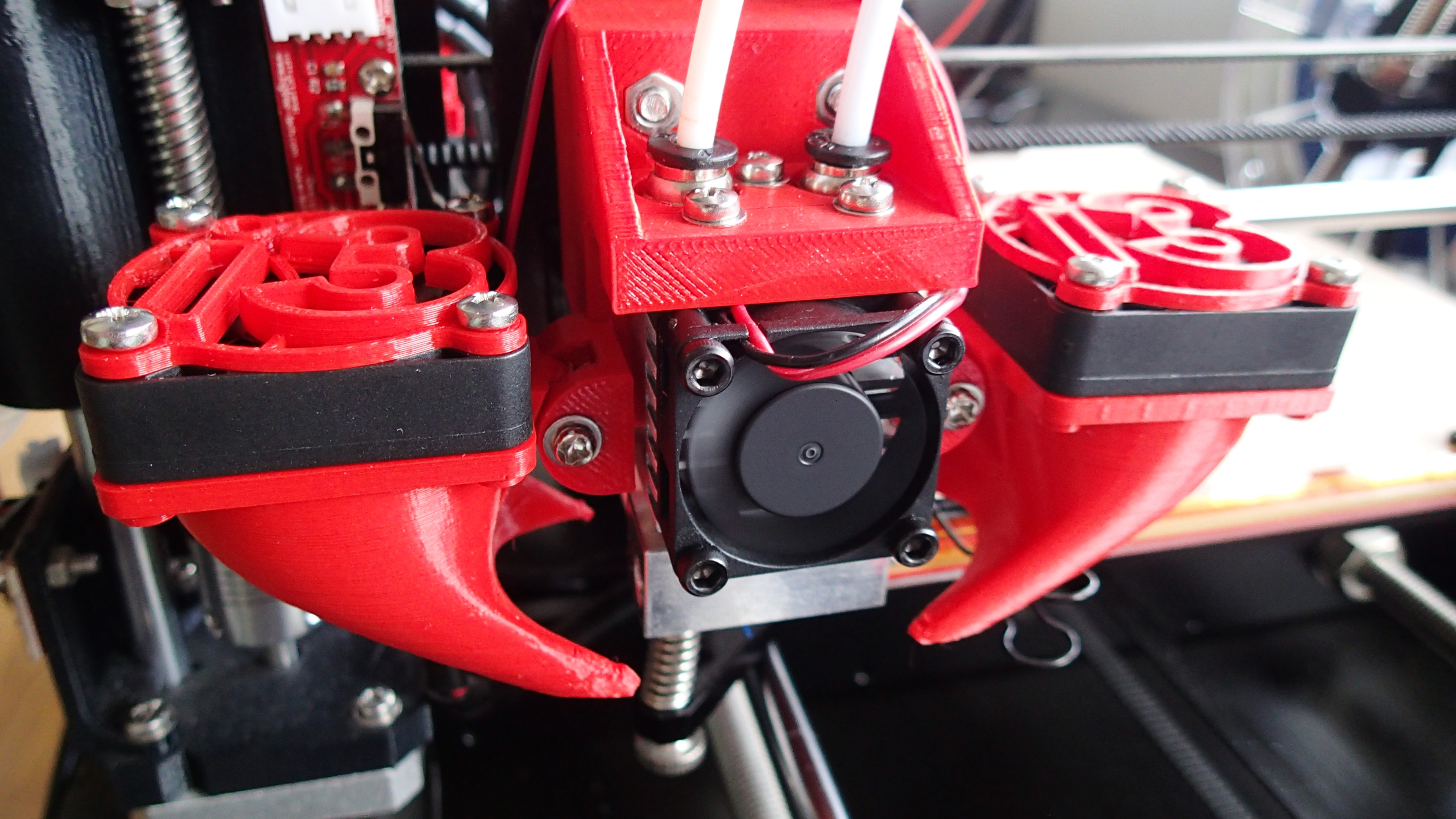
After completing these steps, the part should look like in the picture below.

On the back of this part there are two openings to place M3 nuts to mount the fans.

Now you can attach the fans with M3x20mm bolts and add M3 washers to distribute the pressure.

At this point we are finished with the assembly of the Cyclops extruder.

Now we need to extend the wires of the fans to be able to connect it to the RAMPS controller board.

I hae used around 4 x 70 cm of 0.14 mm2 red and black wires, shrink tubes and a jumper wire cable housing and connector cramps.

Solder the wires of the two print cooling fans together.

I have used a heat gun to shrink the wraps around the wire soldering, but you can also do it with a cigarette lighter.

Extend the wires of the heat sink fan of the extruder and at the other end attach the jumper wire housing. This is because I will be connected it to the RRD fan extender. The print fans wires will connect to the D9 connector on the RAMPS board and do not require jumper wires.

This is the pinout schematic of the RRD fan extender that is connected to the RAMPS board. The extruder cooling fan will be connected to PIN 11 of the Arduino and we can use PIN 6 as output of the controller fan to cool down the stepper driver MOSFETs. 12V can be tapped directly from the RAMPS board. A more complete description on how to connect the RRD fan extender to the RAMPS board can be found here.

The print cooling fans can be connected directly to RAMPS board PIN 9 output, which is located between the extruder heater (10) and heated bed connectors (8).

Connect the extruder thermistor to T0 on the RAMPS board.

Below I have included changes that were made to the Marlin 1.1.5 firmware.
Configuration.h
On line 121 define the MOTHERBOARD type to E(xtruder) F(an) B(ed) type
#define MOTHERBOARD BOARD_RAMPS_13_EFB
Line 136 defines the number of extruders. This needs to be changed to 2.
#define EXTRUDERS 2
On line 139, uncomment this setting to enable Cyclops single nozzle.
#define SINGLENOZZLE
I had defined offset for Chimera extruder. These lines (214, 215) can now be commented out.
//#define HOTEND_OFFSET_X {0.0, -17.80}
//#define HOTEND_OFFSET_Y {0.0, 0.2}
The temperature sensor definition on line 289 for the second extruder can be reset to it's default value of 0.
#define TEMP_SENSOR_1 0
Configuration_adv.h
Uncomment line 184 to enable cooling fan for the MOSFETSs on the RAMPS board.
#define USE_CONTROLLER_FAN
We can use PIN 6 from the RRD extender for that purpose. This is located on line 186.
#define CONTROLLER_FAN_PIN 6
On line 188 you can slow down the fan a bit. In my case the vale of 255 was making a lot of noise.
#define CONTROLLERFAN_SPEED 175
Line 215 defines the extruder cooling fan pin. This value can be set to PIN 11 which matched the second output of the RRD extender.
#define E0_AUTO_FAN_PIN 11
After I was done with the uploading of modifications to the Arduino board. I started to print this dual extruder test. It's great to be able to print without the need for the calibration of the second nozzle.
