In this part we will focus on the X-axis, which is the most complicated axis of the printer. The X-axis is in direct connection to the Z-axis and it also supports the extruder.
The standard library from the Prusa i3 Rework do not offer the possibility to adjust the tension of the belt and they don't support the 8 mm lead screws, so we are going to download Prusa Steel Leadscrew X-Axis system. To build the first part of the X-axis we will need:
- X-axis idler
- X-axis motor
- X-axis idler pulley with hex nut
- X-axis tensioner
- 4x LM8UU 8 mm linear ball bearings
- 2x TR8x8 lead screw nuts
- 1x 624 bearing
- 6x M3 x 16 mm screws
- 1x M3 x 20 mm screw
- 9x M3 nuts
- 1x M4 x 25 mm
- 1x M4 nut
- 1x M4 washer
- 2x M5 x 25 mm bolts
- 2x M5 nuts
The picture includes some more washers, as I thought thay would be handy as an addition to the bearing, but they are not.

First attach the 8mm lead screw bolt tot the X-axis (left in the picture above) with the M3 x16 mm screws and nuts. Then gently push the 2 linear bearings inside the gaps. Do the same to the X-axis motor (right in the picture above) part.

Next insert the bearing inside the X-axis idler pulley and attach it with the M3 x 20 mm screw and nut. Notice the two M3 nuts next to the bearing which serve the purpose of the stability.

Now gather the parts for the X-axis tensioner.

This part will be inserted into to the X-axis idler as in the picture. The M4 bolt will be used to tension the belt and the M5 bolts are used to hold the 8 mm X-axis steel rods in place.

We can now use the 8 mm drill bit to even out the 4 holes that will be used to insert the X-axis rods.

Before we continue and insert the rods, we will first need to assemble another part that needed for the attachment of the extruder hot end. It is the X-CARRAGE and can be found in the standard Prusa i3 Rework library. Add the linear bearings to the printed part and strap them with the cable ties. This part will end the loop in the belt that runs the X-axis.

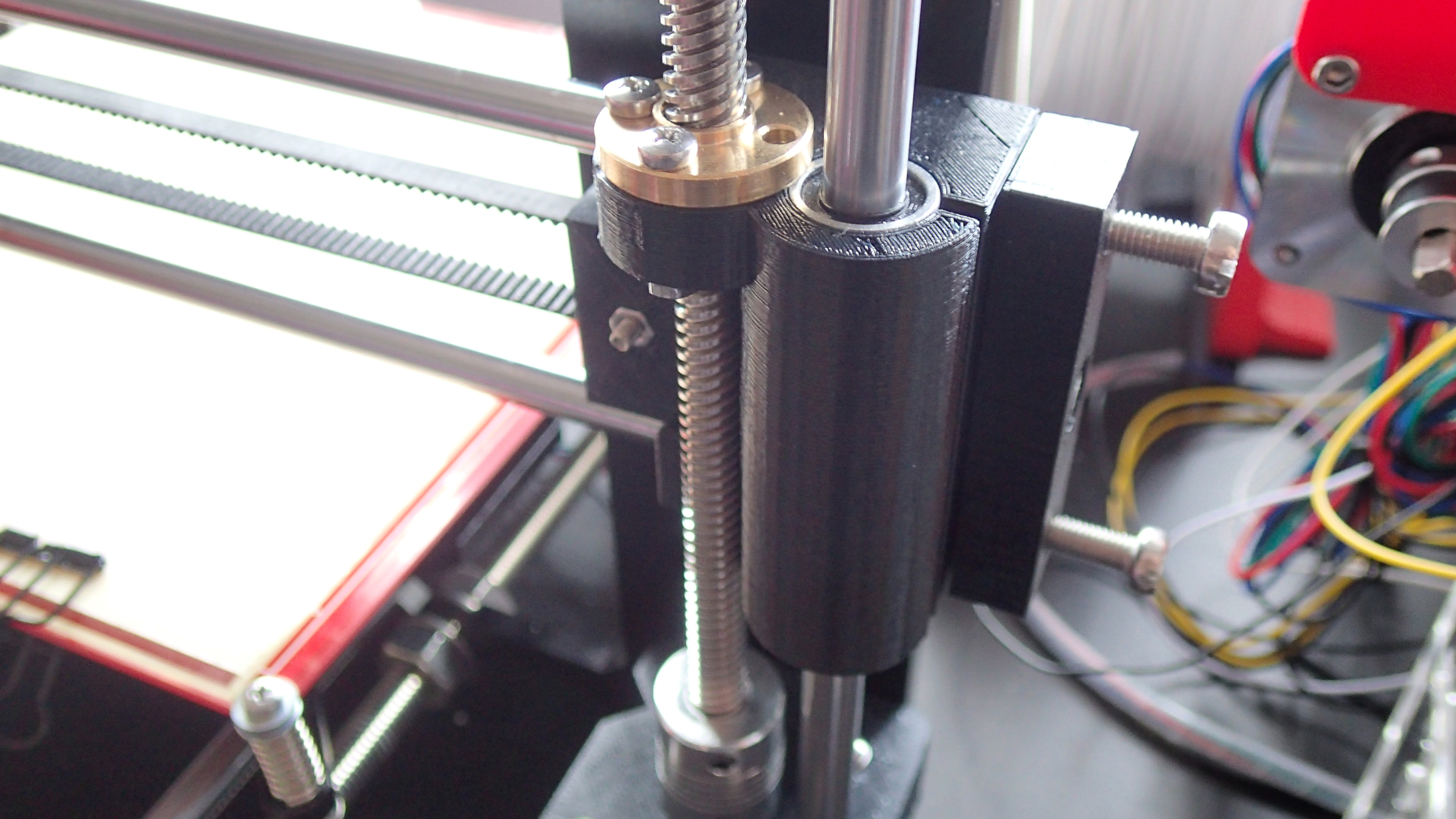
Before continuing to create the X-axis we first need to finish up the Z-axis. Use the 8 mm x 320 mm smooth steel rods and slide the linear bearings of the X-axis idler and X-axis motor parts inside each one of them. You might need to loosen the Z-AXIS-TOP parts to do it. The Z-axis is finished and we are ready to slide the 8 mm x 370 mm smooth steel rods for the X-axis. Do not forget to attach the X-CARRAGE and slide the horizontal X-axis rods through it. The x-axis motor part will go on the left.

And the right side will have the x-axis idler together with the pulley and tensioner parts.

At this point we are ready to attach the X-axis stepper motor with the same GT2 gear pulley as for the Y-aand add the belt. The picture below if from a further stage in the project, but it will give you an idea of how the stepper motor and the belt are attached. You can now use the M5 bolts to secure the X-axis rods in place and the M4 bolt to tension the belt.

And this is how the connection on the back of the X-CARRAGE looks like. The screws serve the purpose of attaching the extruder. We will cover that in detail in the next chapter of this blog.
