The purpose of calibration is to be able to print in correct dimensions and extrude the right amounts of filament. I can give away that it is an endless process, but there is a basis where you must start.
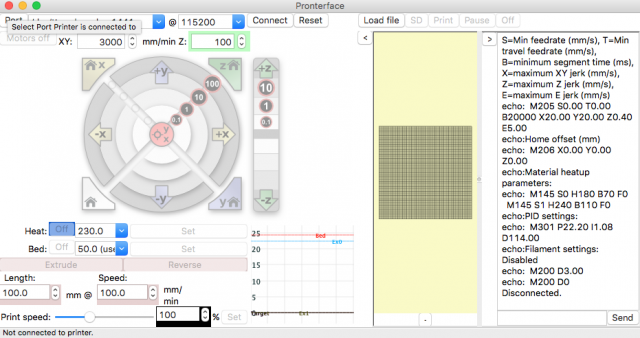
In order to calibrate your 3D printer you will need to install pronterface. It is a free to use program that gives you access all of your printer's core functions and lets you execute G-code commands. In the dropdown list select the correct port and specify the speed, then click the "Connect" button. If everything goes well, you should start to see the temperature graphs of your sensors. With the arrows on the circular board you can move your extruder head in X,Y and Z directions. The white numbers in the black circles indicate how much millimetres your axis shall move. Be careful not to exceed the bounds, otherwise you will stress out the stepper motors, belts and other parts in the printer.
A good starting point is to calibrate the X and Y axes. Move the extruder head to a position somewhere near the left edge and mark the location of the tip of the nozzle with a thin sharpie.
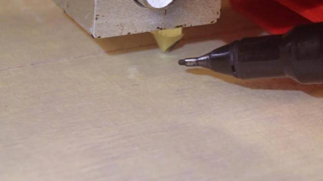
In the outer bounds of the circle in the Pronterface interface click the 100 mm +X area. The head will move some distance to the right. Now mark the location where the nozzle has ended up.
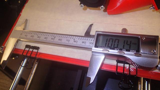
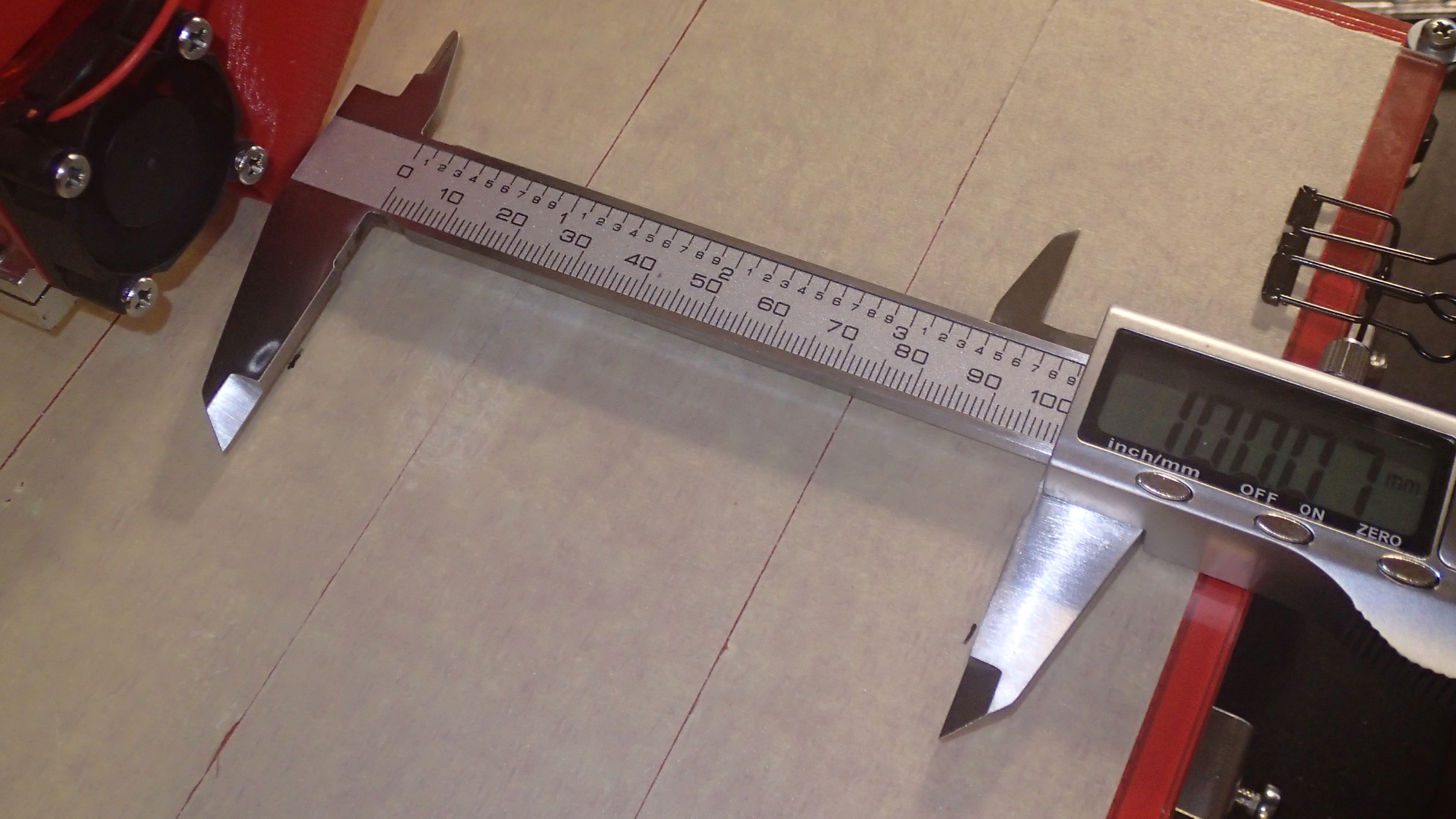
Now measure the distance that the head has traveled. In my case it was 100.14 mm. Of course this is close enough as this method will not let us measure in precision that is more than 0.1 mm. If your distance is different, you will need to change the settings in your Marlin configuration. Go to Configuration.h file and find line 492. The default of this line should look like this:
#define DEFAULT_AXIS_STEPS_PER_UNIT { 80, 80, 4000, 500 }
The comments above the line state:
/**
 * Default Axis Steps Per Unit (steps/mm)
 * Override with M92
 * X, Y, Z, E0 [, E1[, E2[, E3]]]
 */
Which means that the first value is for the X axis. In our case we are using high definition 0.9 degrees per step motor and these defaults are for the 1.8 degrees per step version. So if your head travelled 50 mm you will need to chage the value to 160. The formula to calculate it is:
New value = old value * distance expected to travel / actual travelled distance.
So if the head moved 50 mm the calculation should be:
80 x 100 / 50 = 160
Repeat the same process for the Y direction. You can also use this online calculator to help you with this.
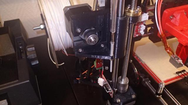
Next we will calibrate the Z axis. This is a bit trickier. First make sure that the extruder is outside of the bounds where moving in the Z direction can touch the glass on the printbed. measure the distance from the bottom of the Z-axis stepper motor to the top of the smooth 8 mm rod and write down the distance. Now measure the distance on the other Z-axis stepper motor.
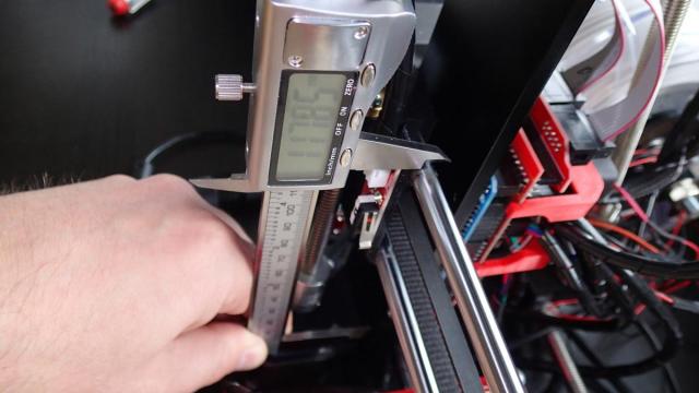
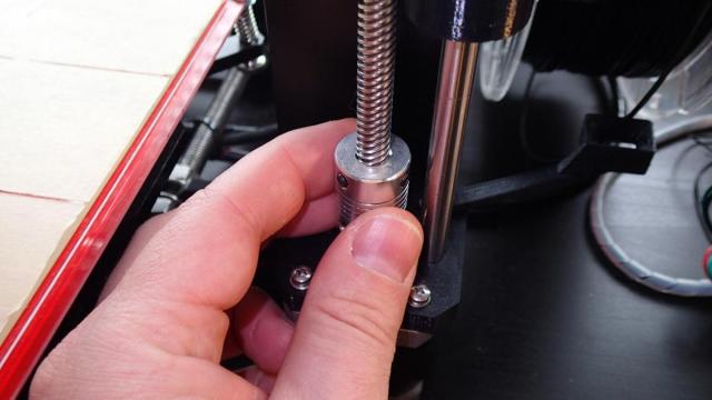
Now turn the shaft coupler till the point where the distance is the same as in the first measurement. Note that when you turn the coupler and the printer is connected the other coupler will automatically turn as well! So make sure the printer is turned off while doing this.
Make sure that the calibration screw that is located on the stepper motor of the X-axis is all the way up and not touching the Z-axis endstop. Move the Z-axis gently (with steps of 1 mm and 0.1 mm) to a position where the nozzle is slightly above the printing surface. Then move the extruder to the middle of the printing bed without scratching the surface. Now place a sheet of A4 paper under the nozzle and while sliding it back and forth move the Z-axis down in steps of 0.1 mm. The correct distance is when the paper is moving with a little bit of friction.
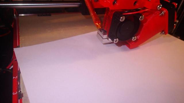
Move the head across the printing bed and make sure that the distances to the sheet op paper are the same. Note that this can vary a bit as the surface is not perfectly flat. Use the calibration wheels on the corners to level the bed.
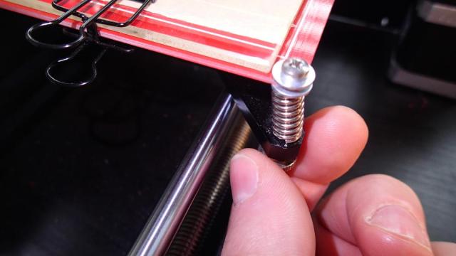
Turn the calibration screw down till the LED indicator of the Z-endstop will lit and you hear a click. Home the Z-axis in Proterface interface by clicking the Z with the home icon and check if the sheet op paper still slides freely. At this point you have successfully calibrated the Z-axis. When you start printing it could happen that the nozzle is slightly too high or too low. You will notice it when the first layer will not stick or get squashed to the surface. When that happens you will need to turn the screw till the point where it is optimal height. One rotation of the M3 screw will lift or lower the nozzle by 0.5 mm.
We will also need a value for the Marlin configuration. This value does not need to be measured, but can be calculated. The lead screws of type TR8x8 lift 8 mm per rotation. This means that our stepper motor will rotate 1/8 times for 1 mm of lift. Our 0.9 degrees per step motor has 400 steps per rotation. In this case we will also need to take the stepper driver in account as it can subdivide each step. The Pololu stepper driver creates 16 micro steps. So our calculation is:
400 steps per rotation / 8 * 16 = 800
You can also use this calculator to verify your results.
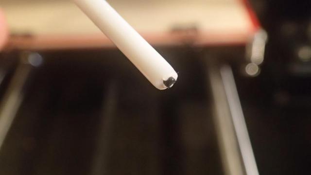
Calibration of the extruder also includes several steps. First pull out the PTFE tube out of the Bowden hotend and cut off the filament that is sticking out so it will be aligned with the tube.
Now heat up the extruder to above 170 °C. You can do that by pressing the "Set" button next to the "Heat:" label in Pronterface. The reason for this is that in the Marlin firmware has a configuration which prevents cold extrusion. You can of course disable it by commenting it out, but I recommend to keep this setting. It is located on lines 383-384:
#define PREVENT_COLD_EXTRUSION
#define EXTRUDE_MINTEMP 170
When the temperature is high enough, extrude 100 mm of filament and measure it. In our case it is 78.81 mm. Again we will need to recalculate the correct value.
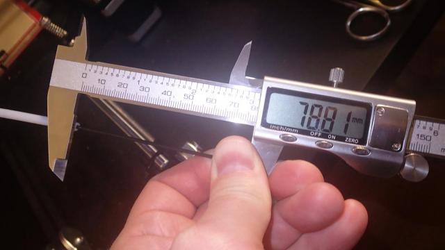
Take the number that is currently configured in Marlin (default is 500) and devide it by the distance that you just measured. Then multiply it by 100 and replace the fourth parameter in the configuration. You can recompile the Marlin firmware and upload in to your board. When you re-extrude 100 mm you should get the correct amount.
In our setup we have 2 extruders, but because we have the same configuration for both, we do not need to specify addition values. The last action that is left is the calibration of the second extruder.
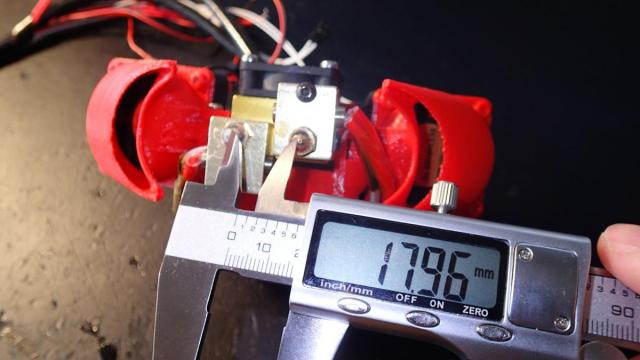
The file Configuration.h contains settings for hotend offsets. In Marlin version 1.1.0-RC3 it is located on lines 91-92 and is called EXTRUDER_OFFSET_X and EXTRUDER_OFFSET_Y. In the version 1.1.0-RC8 the name of the setting is changed to HOTEND_OFFSET_X and HOTEND_OFFSET_Y. It is the distance calculated from the primary extruder. First we will measure the distance between the tips of the nozzles of the extruders. The measured distance is 17.96 mm. It is actually the diagonal distance between the extruders, but because they are mounted in a straight line, we can assume that is it almost the correct X offset. Note that we will need to specify as a negative number because it is to the left of our main extruder. The Y value we will leave as is.
With these values in Marlin RC3:
#define EXTRUDER_OFFSET_X {0.0, -18.0}
#define EXTRUDER_OFFSET_Y {0.0, 0.0}
and Marlin RC8:
#define HOTEND_OFFSET_X {0.0, -18.0}
#define HOTEND_OFFSET_Y {0.0, 0.0}
we are going to compile and upload to the board.
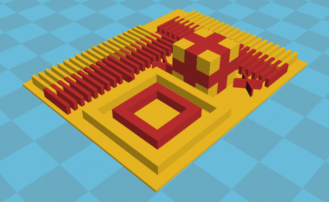
There are various calibration models available to calibrate your dual head extruder. We can use this one: Dual Extruder Sub Millimeter Calibration. You can use Cura to merge the 2 models for dual extruder and print. After printing you can see what is the offset of the extruder and update the Marlin settings. Check out the instruction on how to do this in the description field of this model on the Thingiverse website.