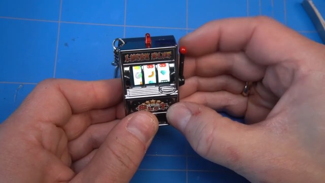
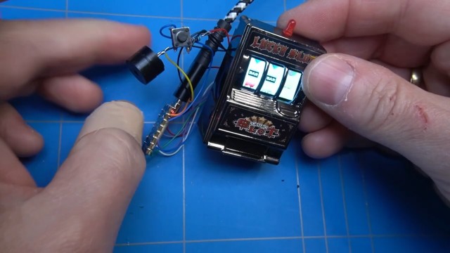
Today we are transforming this mini slot machine keychain into a digital version with an LCD screen.
It all started when I got this keychain slot machine and found it a bit boring. For example, the reels spun simultaneously, and there was no indication when you won something. So, I decided to upgrade it with a microcontroller, replace the reels with an LCD screen, and add some sound effects to it. I'll take you through the whole process, from building the circuit on a breadboard to writing code, fitting everything into the enclosure, and drilling a few holes. Let's see if we can make it work. So read on to see the project unfold!
First step is to take it apart and remove the original internals. The enclosure is secured with four screws so let's remove them.
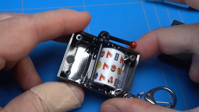
As we open it, the internal mechanism becomes clearly visible, including the reel system and the handle that triggers it. It's interesting to see how these components fit together to make the slot machine work.
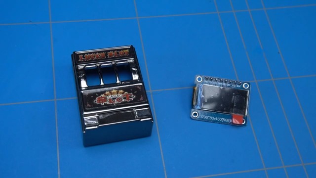
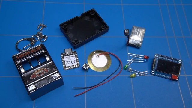
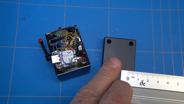
Now that we’ve disassembled it and removed the original components, let’s examine the replacement parts.
I have here a small LCD screen that I was thinking of using where the reels could be displayed. The screen should fit, but there are some edges inside the enclosure that are blocking it. We'll get to that part later and remove them using a Dremel tool.
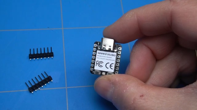
The next part that will be the heart of the project is this Seeed XIAO RA4M1 microcontroller which has the same chip as an Arduino R4, only it is tiny and can be fitted into our slot machine with ease. It has a lot of inputs and outputs that we will use to connect the LCD SPI display, buzzer, button and maybe some LEDs. It even has a battery connection with a charging circuit.
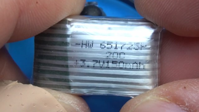
I didn't have any loose batteries that were that small, but I have this old drone that broke down and it's using this small HW 651723P 3.7 volts and 150 milliamp LiPo battery, which I think will be perfect to use in this setup.
To see if the battery was still ok, I used the supplied USB charger and tried to fully charge it. Turns out that it is in full working condition even though I have used this drone ages ago.
So I have collected all of the things that will be needed for the slot machine to work, like buttons and LEDs. Originally I have added a small piezo speaker, but maybe this larger buzzer will be a better solution. We'll see...
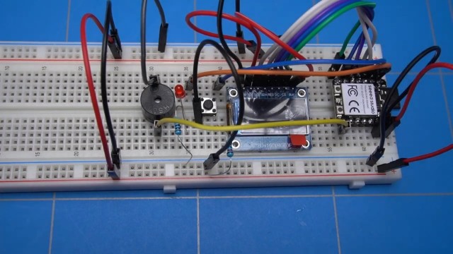
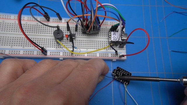
It's time to build the breadboard circuit.
I will start with soldering the pin headers of the XIAO module, then the placement of the LCD screen and this button. I will also insert the buzzer and the LED. We'll come to that later.
First let's check if the microcontroller is working, and it looks as if the RGB LED is cycling through some colors so we must be ok.
Let's hook everything up. First the power and ground for the microcontroller, and this wire will connect to the anode, which is the plus side of the LED. This will be a nice way to indicate if we have won something. I will also connect this current limiting resistor to the ground. Then I will hook up this wire to the switch that will trigger the spinning of the reels. Another resistor will connect the button to 5 volts, putting it in a high state. This wire will connect to the ground, and when the button is pressed it will put the switch in a low state. The 2 wires on the left pass 5V and ground signal to the opposite side of the breadboard. Like this it will be easier to connect them to the display pins. Power also connects to the backlight pin of the LCD screen, we will see later on that it is actually not needed. The other SPI pins will connect to some of the free pins of the XIAO RA4M1 module.
Finally, I will connect the yellow wire to the positive (+) side of the buzzer and then to the ground. It is crucial to get this right, as the buzzer won't work if the connections are reversed.
It's time to get the Arduino IDE working with the XIAO module. To do that we will need to go to the settings and copy the URL of the board for the Seeed Studio wiki page and then in the boards manager we can look for the XIAO RA4M1 module and install it. After a short while we are ready to continue.
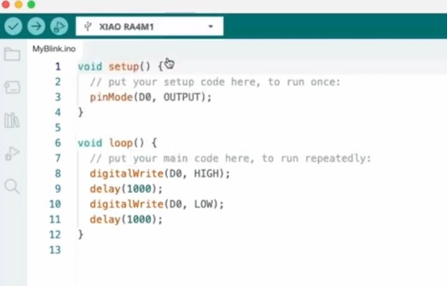
Let's write some test code that will blink the external LED. Select the board and the correct port and upload it. And the Red LED is blinking as expected.
To check if the button is working we are going to define another pin as input. Then we change the working of the LED so that it will be lit only when the state of the button is HIGH. In our case it should be when the button is not pressed. If the button is pressed we will turn off the LED.
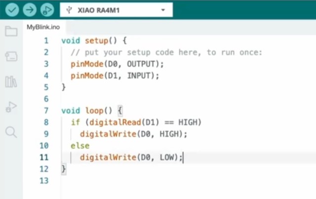
And this is also working as expected. To reverse this functionality and light the LED when the button is pressed we can change the code. And this works as well, pressing the button lights the LED.
Let's continue and do something more exciting, which is getting the LCD display to work.
This display has an SPI interface and we will start by including all of the libraries that are needed for it to work. Then we define all of the pins of the interface as constants. Do some initialisations on the screen and fill it to black, then we will write some text to display on it. Compile it.. and... there is an error. Which is completely valid as we did not install these libraries.
We can do that now.
When we compile the project, it gives us another error inside the Adafruit GFX library. The error says that there is a file that can not be included.
We can comment out the line where this file gets included, and somehow it compiles now. Compiling the project again shows yet another error that the variable tft is not defined. It seems that I forgot to do it. Let's add this line of code that will initialize the tft screen and.. it's a success. We have no more errors.
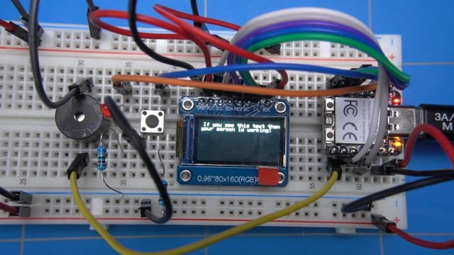
But we are not doing anything yet, so let's add a line that will show some text on the screen.
After compiling the code we can now see the text is printed on the display. And the button is also still working. Nice!
Let's continue to make sure that we can use the buzzer. There is a library called cutebuzzer which includes some sound effects that can be called by using the play function, like in the highlighted area in the code.
After the code compiles we can now hear this chirping sound effect.
A more practical way is to play a sound when we press a button, this can be achieved by moving the play function inside the part where we handle the button press. And this works as well.
Ok, now we can address all of our peripherals, it's time to focus on creating the fruit machine. First I am going to start by finding some fruit machine graphics that we can use. This website offers some nice symbols and they are free to use as long as you add an attribution to the website. Let's download a couple of PNG images and see how we can display them on our LCD screen.
After experimenting a bit, I have found out that the LCD display can show images that are encoded in RGB 565 format, which is a 16-bit encoding. It means that we have 5 bits for RED, 6 for GREEN and 5 for BLUE. The PNG files that we downloaded are 24-bit images so they need to be converted.
I have written a conversion script in python that converts the image into an array that can be used inside the Arduino code. It accepts a couple of parameters as image name and the pixel size of the output image.
We can now copy the output into the Arduino code next to a couple of supporting functions to show the image on the display and compile. All of the code that I am writing now is available for free download from my github repository.
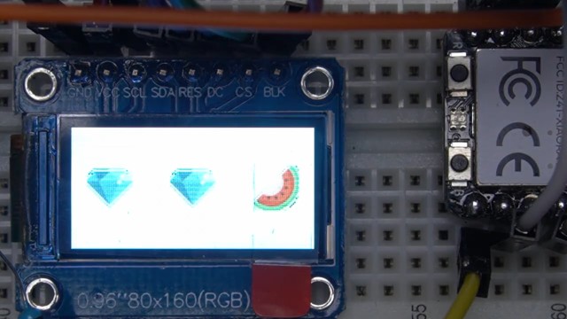
At this point it just shows 3 static images. The idea is that the original enclosure will show the reels with symbols just like this.
Let's try to get some movement into them and make them scroll. For that I have changed the loop function so the image is displayed with a small black box on the bottom of it. This way when we redraw the image to another position and it will clear the previous image that is being redrawn. I have done this for all of the reels.
This part of the code is changing the vertical position of the images by 10 pixels every time the loop is executed.
  // Draw a white square under the symbols to prevent dragging
 if (!offset1) tft.fillRect(xPosReel1, yPosReel1 - 40 + offset1 + 30, imageWidth, 10, ST77XX_WHITE);
 if (!offset2) tft.fillRect(xPosReel2, yPosReel2 - 40 + offset2 + 30, imageWidth, 10, ST77XX_WHITE);
 if (!offset3) tft.fillRect(xPosReel3, yPosReel3 - 40 + offset3 + 30, imageWidth, 10, ST77XX_WHITE);
And this is how it looks on the display.
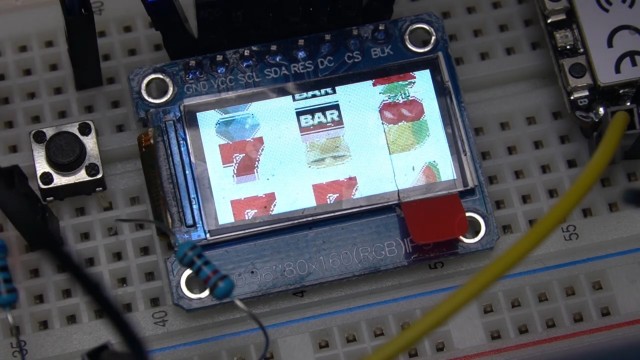
Another thing that I would like to do is to change the background color to white, as I think that this will look nicer. It just requires adjustment in one line of the code, the rest stays the same for now.
tft.fillScreen(ST77XX_WHITE);After uploading the code the 7 symbols on the reel will look like this. They fit perfectly in the cutouts of the enclosure.
Let's add a couple more symbols to the code and create an array of those symbols so we can reference them more easily.
Here I am defining all of the reels and what the order of these elements will be. It's easy to change them for your own liking.
// Define the reel arrays based on winning probabilities
const int reel1[] = {CHERRY, LEMON, ORANGE, PLUM, WATERMELON, BELL, DIAMOND, BAR, SEVEN, CHERRY, ORANGE, PLUM, WATERMELON, BELL, DIAMOND, BAR, SEVEN, CHERRY, PLUM, DIAMOND, WATERMELON, BELL, ORANGE, SEVEN, LEMON, BAR, CHERRY, SEVEN, WATERMELON, BELL};
const int reel2[] = {ORANGE, LEMON, PLUM, CHERRY, WATERMELON, DIAMOND, BAR, BELL, SEVEN, LEMON, CHERRY, ORANGE, WATERMELON, PLUM, SEVEN, BAR, DIAMOND, BELL, SEVEN, ORANGE, WATERMELON, LEMON, BELL, CHERRY, PLUM, DIAMOND, BAR, ORANGE, SEVEN, LEMON};
const int reel3[] = {PLUM, ORANGE, CHERRY, LEMON, WATERMELON, BELL, BAR, DIAMOND, SEVEN, SEVEN, ORANGE, PLUM, WATERMELON, LEMON, SEVEN, CHERRY, DIAMOND, BAR, SEVEN, BELL, WATERMELON, CHERRY, LEMON, ORANGE, PLUM, BELL, DIAMOND, SEVEN, ORANGE, BAR};
The symbols are drawn here, depending on what it is. I have disabled the scrolling function for now and just show a random symbol after the microcontroller is turned on or on reset.
By pressing the reset button on the XIAO microcontroller the reels are now rearranging.
To make it more realistic, let's add an animation to the reels so it will look like they are spinning.
It's a simple for loop for each of the reels that is repeated when the index of the reel is reached. The time for each spin of a reel is randomised.
This is how it looks when we upload the code and spin the reels by pressing the button.
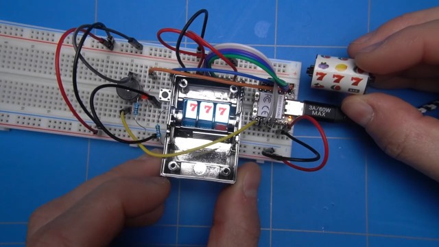
When there is a cherry symbol on the first reel, or there are 2 or 3 same symbols in the resulting spin, then there is a win. A sound is played and the LED is blinking.
Let's spin the reels and hope that we win something. Look at that! three sevens, it seems we have hit the jackpot! Too bad it was not in a real casino. But what is important is that we can hear a win sound and the LED is blinking, and that is our win!
It's time to place the contents of the breadboard into the enclosure. How about we start with the display and try to fit it in.
There are some protrusions inside the casing preventing the LCD screen from fitting in properly, so I will sand them down to resolve the issue.
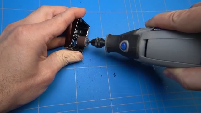
It's a bit messy, but the screen seems to fit now.
I am curious how the screen will look when it's turned on inside the small housing. Let me quickly connect the wires by using these half jumper wires . I will also reattach them on the breadboard where the screen was connected.
Let's see if our screen is working by connecting it. And it looks like we are still in business.
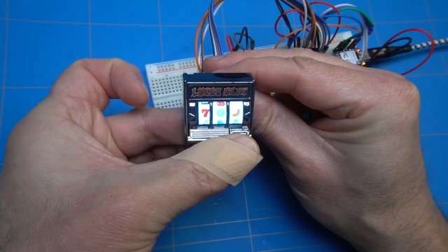
Placing the small housing on top of it. This is how it looks, but I am noticing a small offset as the symbols are slightly to the right, but we can fix that later in the code by changing the horizontal offset of the reels.
Why don't we continue to place the rest of the components from the breadboard inside the enclosure. I will use another XIAO module as the one on the breadboard already has pin headers soldered onto it. It should fit nicely on top of the LCD screen. I am guessing that the battery can go on the bottom and the LED somewhere on top.
Not to forget, we will also need a power switch that will cut the power to the battery and I will also need to figure out how to trigger the spin button by using the lever. The buzzer will also need to fit somewhere
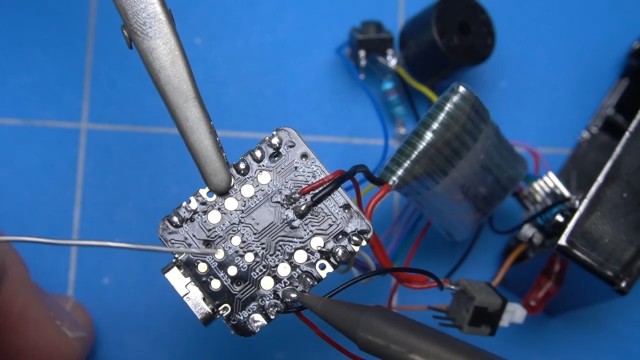
I will use this thin solid wire to make the connections. Let me cut a bit to work with.
Now comes the tedious part of connecting all of the wires to the controller and then soldering them. I will not show all of it here, but you get the idea. When finished, I will cut off the wires that are sticking out.
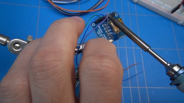
It's time to solder the wires on the microcontroller to the display. Using the helping hand to hold the screen securely makes soldering the wires to it much easier.
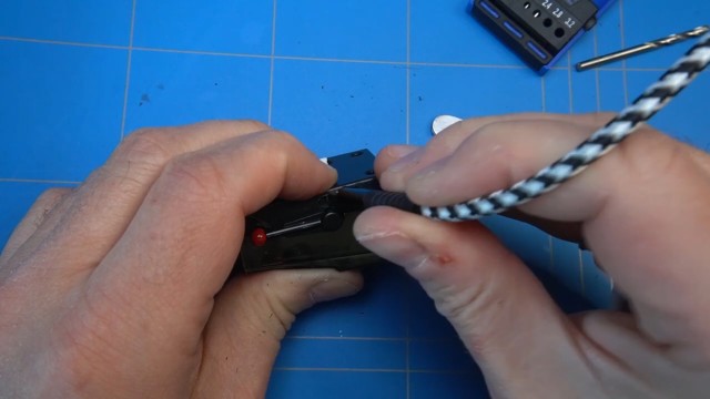
After uploading the Arduino sketch it seems to be working, but since we don't have a button the reels are always spinning. Let's fix that.
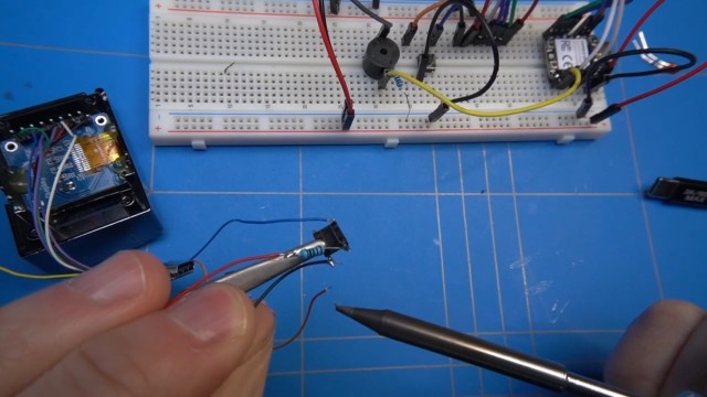
Next, I will solder this 10 kilo-ohms resistor to one of the wires and when I hold the end of it to the power pin on the display, the spinning should stop, as we are enabling it on the low state in our code.
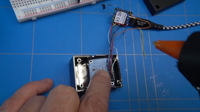
To have a sense that something is already finished, let's fasten the LCD screen to the enclosure with some hot glue.
I was thinking of placing an LED on top of the cabinet. It will blink when there is a winning combination.
It's a 3mm LED and the legs are 2.5 mm apart. Let's drill 2 small holes with the dremel tool. And the LED fits nicely like this.
I have made a mistake by soldering the 10K resistor directly to the wire, but it has to be soldered to the switch first. Let me fix that.
A red wire soldered to the pull-up resistor indicates that it connects to the power pin. The other pin on the switch directly connects to the ground. When the button is pressed, it grounds the pin, causing it to switch from a high state to a low state.
Let me solder the wires from the tactile switch to the power and ground pins on the LCD screen.
Pressing the button does indeed work as intended.
The next step is to wire up the buzzer. There are just two wires, so it's simple enough.
Time to solder the connections to the LED. We will also need a current limiting resistor. I am using 680 Ohm here, because of the max current rating of 8 milliamps on the input pin of the SEEED board.
Well, I think that's it. All of the components are wired up. It looks like the fruit machine is working. The only thing that is left is the battery and the on off switch.
First I will solder the wire to a switch. Then the positive terminal will also connect to the switch.
So now we can solder the wire from the switch to the battery pad on the XIAO board and the other wire goes from the battery directly to the negative connection.
But somehow when I turn it on, it does not work. What could it be? Is the battery not charged?
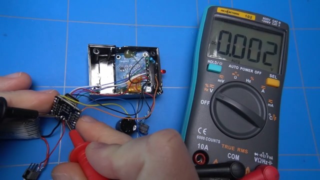
Well, it seems like the battery is dead. I still have another one, let me quickly swap it.
When I now turn it on, it looks like there is some activity, but nothing is visible on the screen.
After plugging in the USB cable and letting it change for a while it seems to work fine. However when I unplug the power the screen goes back to dim. It looks like there is not enough voltage being provided.
I think that I found the problem. The battery provides 3.7 Volts of power and somehow when you tap the voltage out of the board to the screen the VBUS does not generate enough juice. There is another voltage pin labeled 3.3V. Let's solder the wire to that one.
When you now turn it on, the screen has vivid brightness and everything is working fine.
Next on the menu is to get the spin button working by using the lever. It needs to be just in the correct position and it can be triggered using the old mechanism that spun the reels. But first let's secure the rest of the components inside the enclosure, like the battery. Using hot glue seems to work fine.
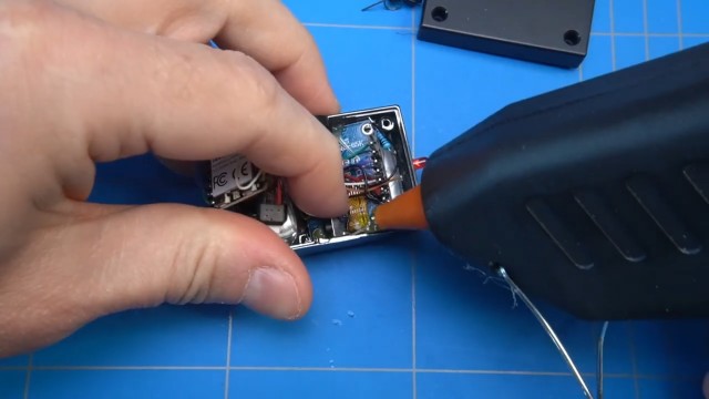
Now let's put some hot glue and secure the button. It was somewhere in this location. Let us try to use this double sided tape to secure the microcontroller.
I believe the on-off switch will fit somewhere around here, though it's starting to feel a bit cramped. Well, it kind of fits and when I pull the lever, it's even spinning the reels. We are almost there...
It's time to take measurements for the placement of the on-off switch and drill the hole.
Another hole is needed for the USB-C connector.
Famous last words... it is done! Time to enjoy it for a bit.