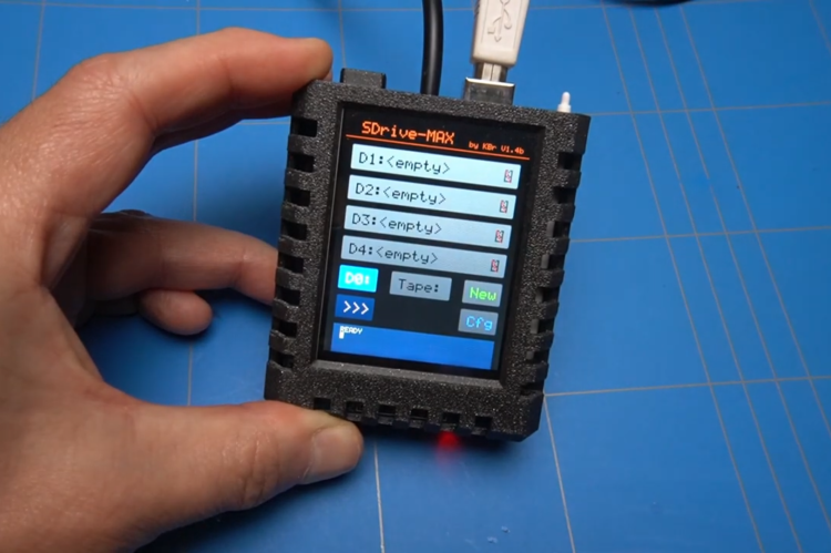
Watch the video here or read on...
To build the SDrive-MAX you will need an Arduino Uno and a display module which includes an SD card reader like the 2.8 inch ILI9341 display module.
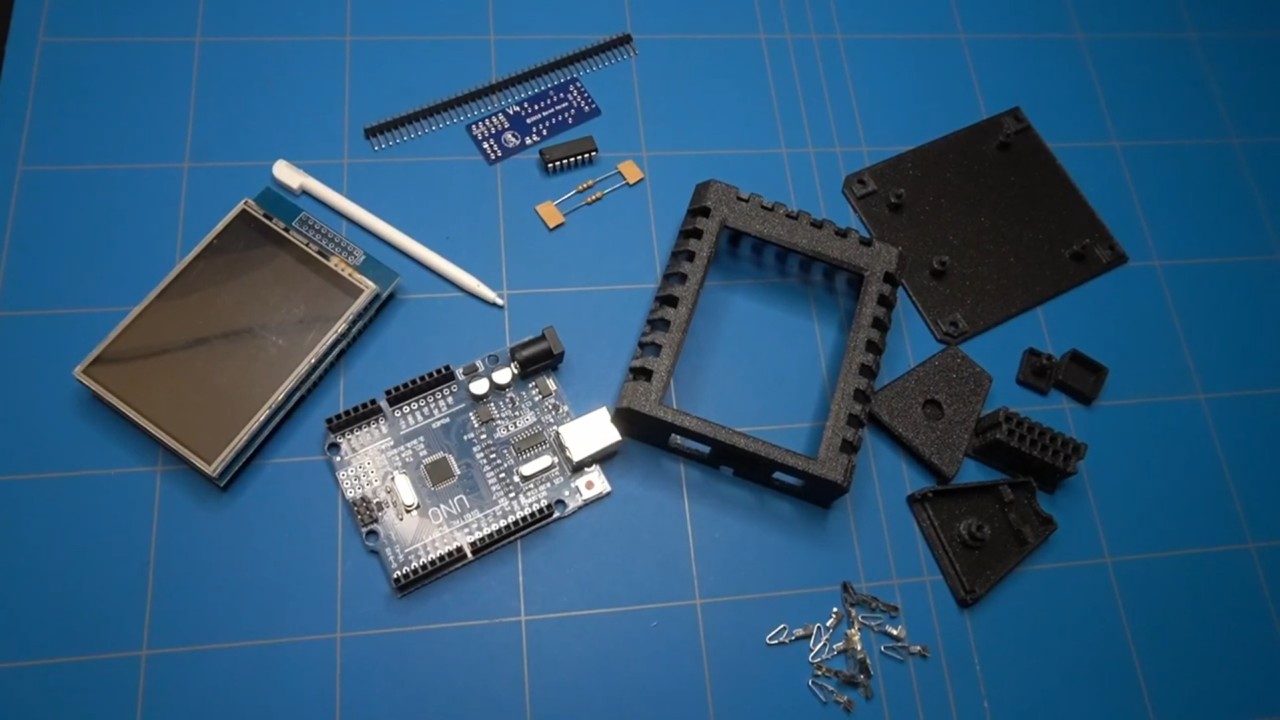
Optionally you might want to add a module called UNO2SIO, that will allow you to connect the SDrive MAX next to other Atari SIO peripherals, like a floppy disk drive or a printer.
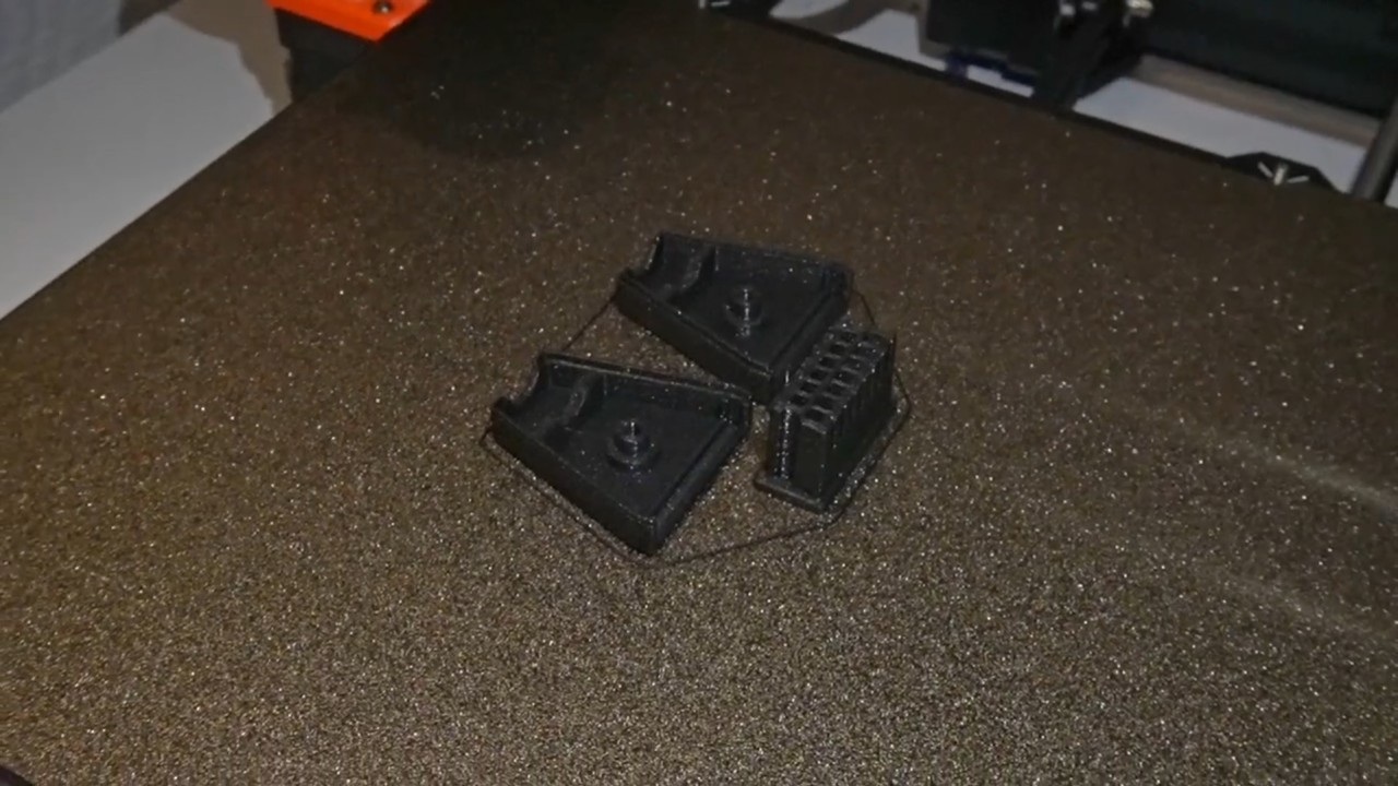
It's actually also a must to 3D print an SDrive-MAX enclosure for it. There are many available designs that can be downloaded for free. And you will definitely need a SIO connector.
As with most retro peripherals, these are not produced anymore. The description mentions which contacts to use for this plug. Apparently the contacts that can be pulled out of an AT power supply motherboard connector fit perfectly, but if you don't want to demolish your power supply plugs, the Molex 8500106 connectors can also be purchased separately.
Let's start with the assembly of the UNO2SIO board. This will allow the SDrive-MAX to connect alongside other Atari SIO peripherals like disk drives and printers. It's a small board that goes on top of the Arduino pin headers.
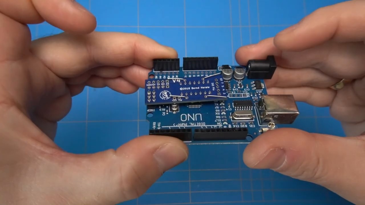
This board uses one single IC 74LS07, which is a buffer that is used to interface between the Arduino UNO microcontroller and a SIO device. It needs 2, 4.7KΩ resistors. This board also offers connections that you can use to solder the wires that connect to the SIO plug. And as an extra feature you can use external 5V voltage to power the SDrive Max or the 5 volts that is provided by Atari on the SIO port. I intend to always use an external power adapter, so no extra jumpers or switches are needed to be installed on this board.
We will also have to solder a 4 pin header to the Arduino board so the UNO2SIO PCB can connect to it.
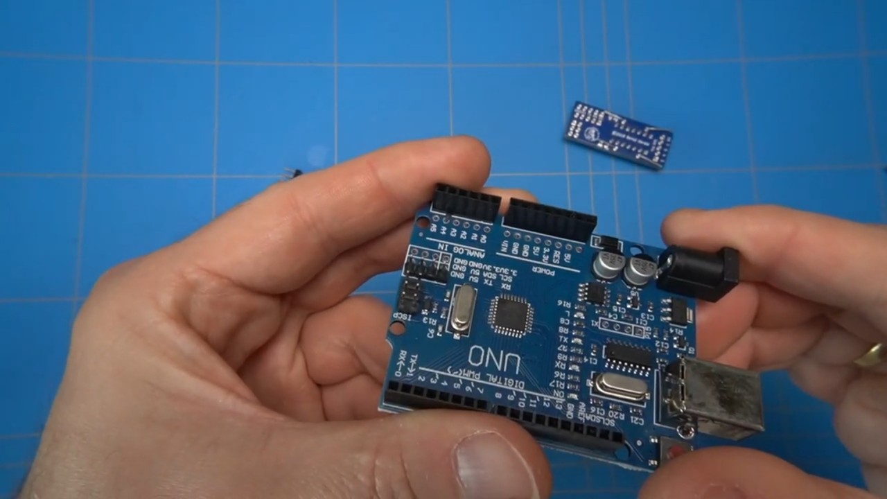
To solder the 4 pin header I will use a sticky tack to hold it in place. And clean it up with some IPA. We can now proceed to solder on the SIO wires and the connections that attach to the Arduino board.
For the SIO lead I got a MIDI cable because it was cheaper to get instead of a separate 5 wire lead.
Next step is to strip the wires. There is another lead that needs to be soldered to the Arduino board A5 pin. I will use this yellow wire to make the connection. Check this post for more details.
Finally we can proceed to solder the 5 leads to the SIO connections on this small board.
Align the UNO2SIO board with the Arduino's pin headers, then solder it in place. And of course we can't forget the yellow wire that attaches to the A5 pin on the Arduino.
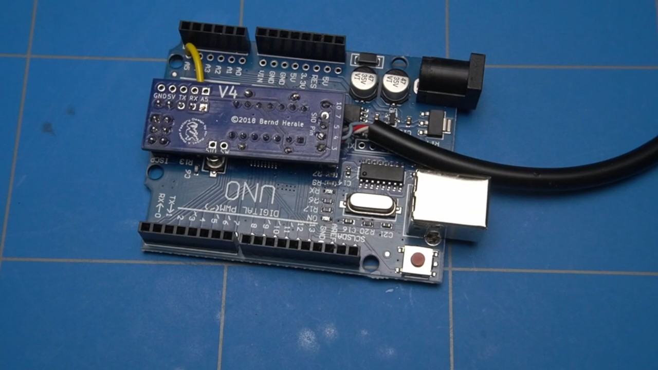
Let's keep it nice and tidy and clean up the board with IPA and trim the ends of the leads that are sticking out.
Now proceeding to the other end of the cable where the actual SIO connector will be placed. First step is to strip the wires.
The MOLEX connectors should then fit into the openings of this 3D printed SIO plug.
I have these crimping pliers, and I'm optimistic that one of the jaws will successfully crimp the connectors to the wires. Well maybe with a little bit of help from the nose needle pliers.
Now it's just the matter of fitting them inside the plug. Well.. easier said than done...
Let's hope that I can push them a bit further with this small screwdriver.
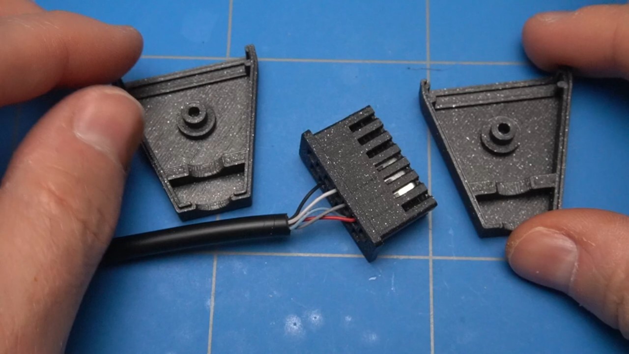
Before we close up the SIO connector there are some holes that need to be punched as the 3D printer did not do that. Or maybe this was by design?
I will use this small screwdriver to do this. Let's try to push it in. We will worry about the loose cable inside the connector later.
First it needs a 3mm nut and then a small 3mm bolt. Apparently the hole is a bit too small. I will predrill that later. For now, let's just quickly secure this screw so the connector will be functional.
We are more or less done with the electronic part. Let's now focus on the software part.
PROGRAMMING
I will be doing the Arduino programming inside Ubuntu Linux. This is because it's needed in order to compile to the latest version of the SDrive-Max project. It is not a dedicated Linux machine, but a Virtualbox instance that is running on a Windows host, but it works fine.
You can also program the SDrive MAX in a different way by following the steps described on the atari8bit.net website, but I will not dive deeper into it in this video.
First let's prepare all the tools needed in order to compile the project.
This is the github repository of the SDrive-MAX project. We can see all of the created releases in this overview. And version 1.3 is the latest. There are a couple of older releases when we scroll down this page. But when we go back to the main page and click here we see that there is another branch, called version 1.4 and I believe that this is the latest development because it is several commits ahead of the master branch. We can download this version of the code and unpack it.
Now we are going to install a couple of tools. The first one is XA65, which is a 6502 compiler.
sudo apt install xa65Other tools that we will need are the AVR toolchain and libraries that will help compile and program the Arduino board.
sudo apt install avr-libc gcc-avr makeTo compile the SDrive-MAX code we change the Downloads directory, then the extracted sdrive-max folder and type
make allAfter a while we will have a compiled binary that we can now write to our Arduino UNO.
There are multiple versions of the SDrive-MAX binaries compiled into various versions based on the screen that it is using. I have one that uses the ILI9341 chipset. Inside this directory there are 2 files that we need to upload to the Arduino.
The first one is eeprom_writer.hex. This is the exact avrdude command to do this on my machine.
avrdude -V -carduino -pm328p -P /dev/ttyUSB0 -U flash:w:eeprom_writer.hexAfter the programming cycle is finished we can unplug the USB, connect the screen and power it up again. We will see a couple of progress bars of writing and verifying the EEPROM on the screen.
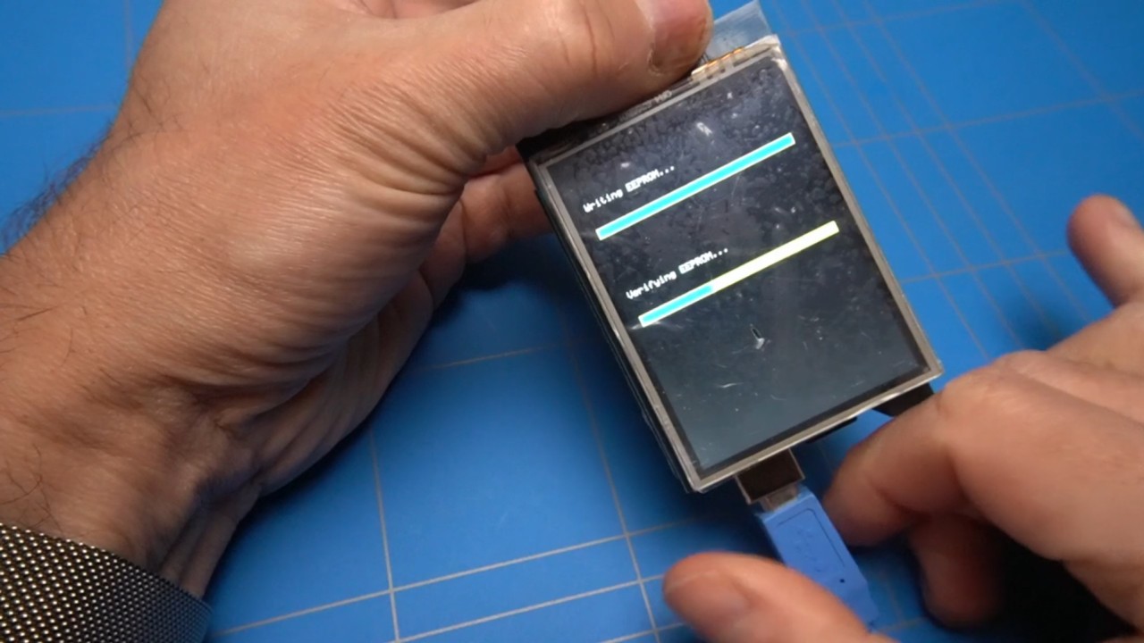
After this is finished, we can proceed to the next part of uploading the other file, which is called SDrive.hex
avrdude -V -carduino -pm328p -P /dev/ttyUSB0 -U flash:w:sdrive.hexWhen a cross is displayed, then it was a success and the SDrive MAX was successfully uploaded. Touch the calibration crosses and then tap one more time to enter the interface.
Perfect, everything is looking great!
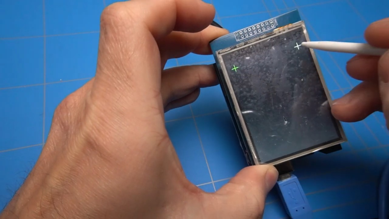
Now it's time to prepare an SD card for Atari disk or cassette tape images. The SDrive-MAX supports SD cards up to 32 GB. Using a larger card will result in an error.
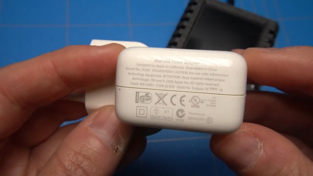
However when I formatted this 16GB SD card as FAT32 as mentioned in the instructions it gave me another error. A search inside the issues of the SDrive-MAX repository yielded that most newer SD cards don't initialize well. It seems that there is no solution to this problem as of yet, but I have noticed that when you power the SDrive MAX using an 1 ampere USB power adapter like this one from Apple, it does not give me any errors. Directly connecting to an USB port on the computer also does not show any errors. So it may have to do something with the power supply.
Fortunately, I have found a smaller 2GB SD card where that problem does not occur. First, we need to copy the sdrive.atr file from the SWorld folder inside the GitHub repository. After that, we can copy the other image files. The order in copying these files does matter.
Before placing the Arduino and the screen inside an enclosure, I want to add one last thing to this setup. Which will be status LEDs that will allow to see if the SDrive-MAX is on, and if there is any activity on the SIO port. This is actually a suggestion from Devzine, who is the author of this mod and also designed a nice circuit board for it. The links to his project and website are in the description. For now I will just hack in the LEDs, but will certainly get one of these nicely designed PCBs in the future.
First I have created the circuit on a breadboard and made sure it's working correctly, now you can see me soldering all of the wires and LEDs to the Arduino board.
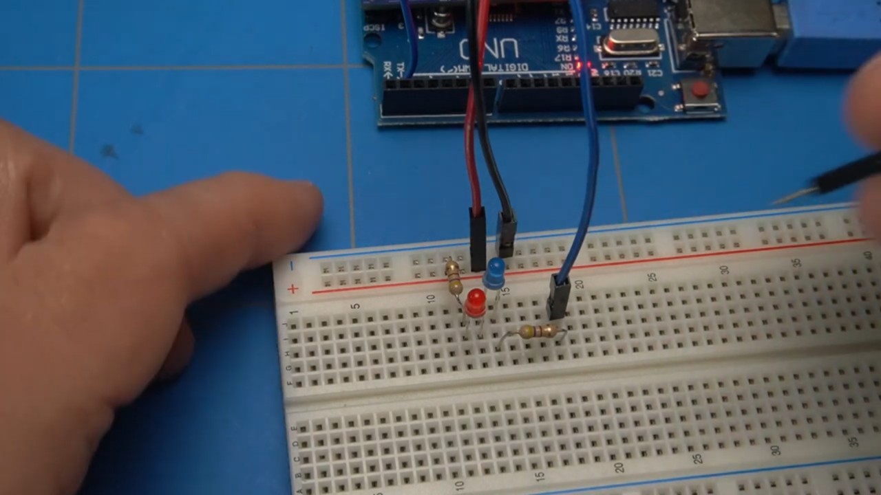
After connecting it to an Atari, which is off-screen, you can see that the red power led is on and the blue LED which indicates disk activity, is flashing.
It is time to pre-drill some holes in the enclosure for the LEDs and put the Arduino with the screen inside of it. That was easier said than done, because the enclosure is really tidy and there is a specific way to insert it.
First you need to insert the screen into its slot and then, carefully maneuver and fiddle with the Arduino Uno board to fit it snugly into the enclosure. It took me quite some time to get it right, but I will spare you in showing all of the footage that I have recorded. However I am sure that a complete blog post could be made just on the subject. 🙂
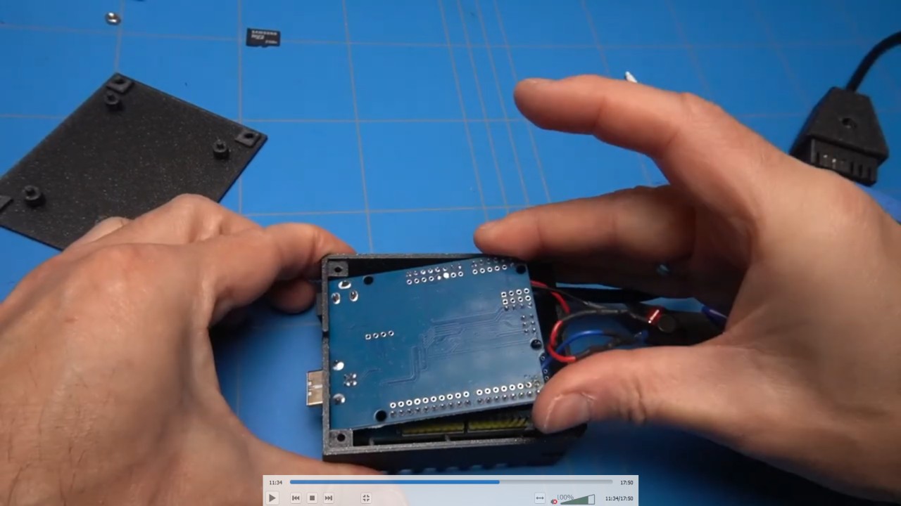
Before we are going to do some tests with the SDrive-MAX. Let's just finish the enclosure and the SIO plug.
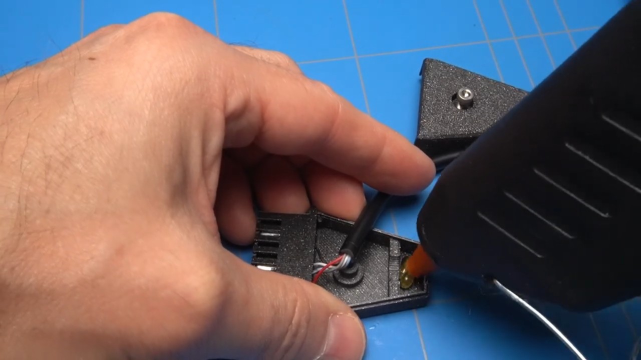
The loose cable inside the plug's enclosure can be secured with a hot glue gun, preventing it from being accidentally pulled out. Additionally, I have widened the holes to fit a 3mm screw, ensuring a snug fit.
The back plate of the SDrive-MAX enclosure can be attached with self-tapping screws. I found some that fit almost perfectly. Although they protrude slightly, adding rubber pads will prevent them from scratching any surface or desk where the device is placed.
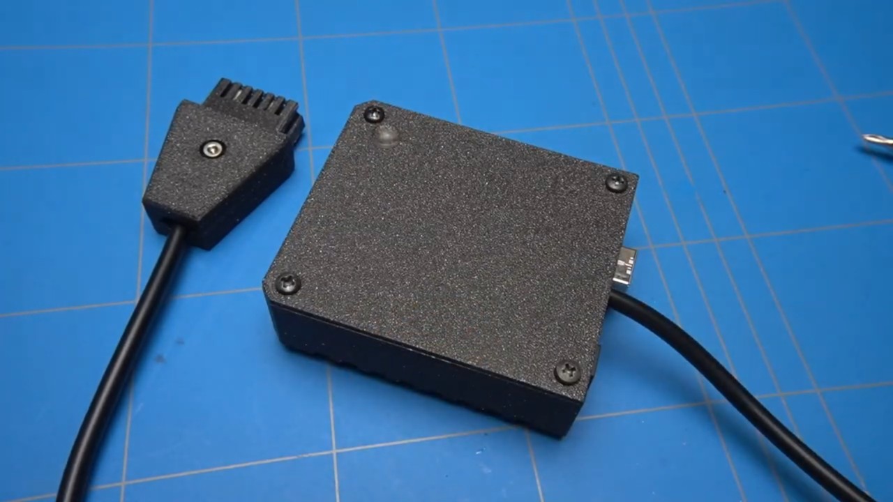
The 3D printed enclosure also includes covers that can be inserted into the power connectors, protecting them from dust and debris.
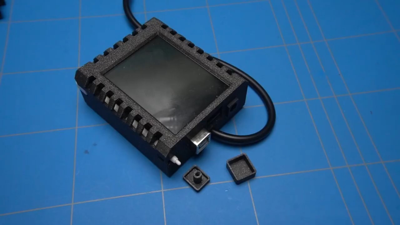
Let's turn on the SDrive-MAX and configure its settings. If your screen is unresponsive to touch input, you can reset it by holding the screen while plugging in the power. Then, calibrate the screen by tapping on the crosses as usual.
The default screen orientation is a bit awkward, with the plugs facing the front of the device. Fortunately, you can rotate it. Tap the configuration button, select rotate, press save, and redo the calibration. The screen should now be rotated, and Devzine's status LEDs will be clearly visible. Additionally, the device will remember the rotated setting when you reconnect it, which is very convenient.
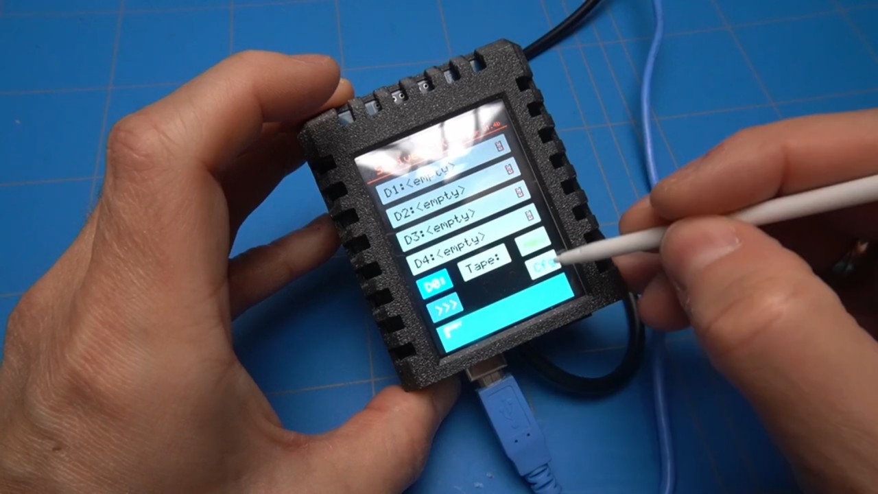
Finally, it's time to test and play with the device. I'll start by connecting it to my Atari 800 XL computer.
I have connected the SIO cable directly from the 1050 Atari disk drive to the Atari 800XL, and daisy chained the SDrive-MAX back to the second SIO connector on the disk drive. This setup will allow to test if the SDrive-MAX functions properly alongside other SIO devices.
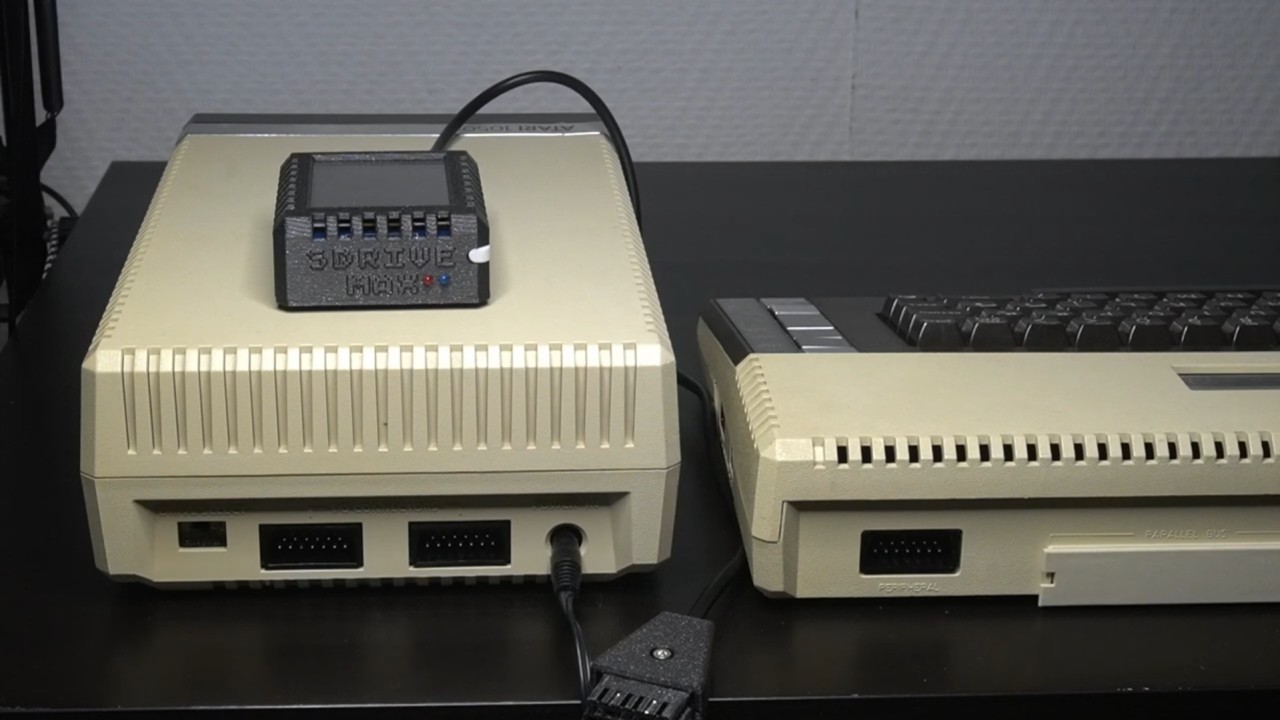
When we turn on the computer without touching any settings on the SDrive MAX it will start up with the default file selection utility called SDRIVE.ATR and it will be loaded using the internal D0 drive.. You can then mount the ATR files into one of the four available drive slots: D1 through D4.
Let's browse through the catalog of games that I've copied to the SD card. Perhaps we can look for Boulder Dash. You can navigate faster by scrolling through the pages using the left and right arrow keys. Ah, there it is! Unfortunately, we can’t see the full names of the files as they are truncated to the old 8-character DOS format.
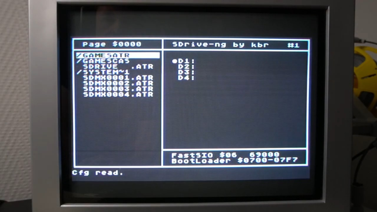
Our selection also shows up on the screen of SDrive-Max.
We can mount the file by pressing ENTER and selecting the drive. Let's choose D1 as it is the boot disk. And this is not Boulder dash, but another game called Boulder Bombers. Oh well.. let's remember that for the next time.
We can now try to copy a physical Atari disk to a virtual one on the SDrive-MAX.
To do that we are going to click on the D1 slot and click on NEW. Then by clicking on the second slot we make the NEW disk D2 drive. This way we can boot from the 1050 disk as the SDrive MAX is now not using it.
You can see here that the source drive is D1 and destination drive is D2, which is the empty disk on the SDrive MAX drive.
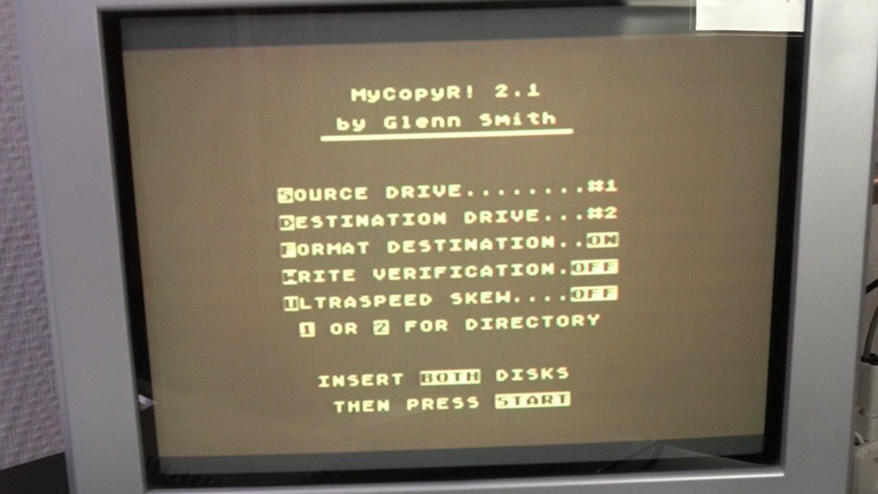
We can now start copying the COPY disk.
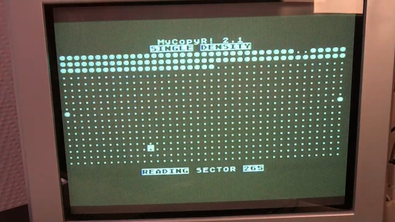
When we take a look on the screen of SDrive MAX we can see that the name has changed to an internal name.
To test it, let's unplug the 1050 drive and connect the SDrive-MAX directly to the Atari. Now, when we mount this newly created disk to the D1 slot and boot the computer, we can see that our copy program has been loaded.
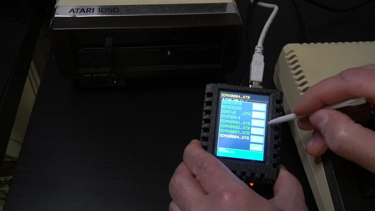
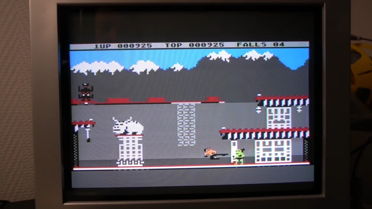
Next, I want to test the SDrive-MAX's capability to function as a tape drive by mounting a .CASsette file. For example, if we select Bruce Lee and then start the Atari computer by pressing the START and OPTION keys, we will hear the famous beep.
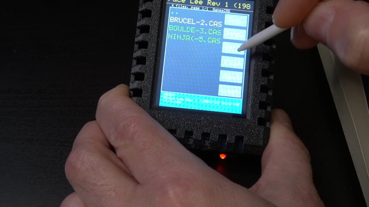
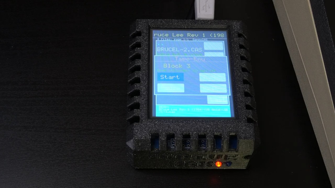
Now, we can click on Start on the SDrive-MAX and then press the spacebar on the computer to initiate loading.
The screen displays the progress by showing how many blocks have been loaded. You don't hear the synchronization beep, which might indicate that it isn’t necessary on the SDrive-MAX.
Now let's enjoy and play the game.
