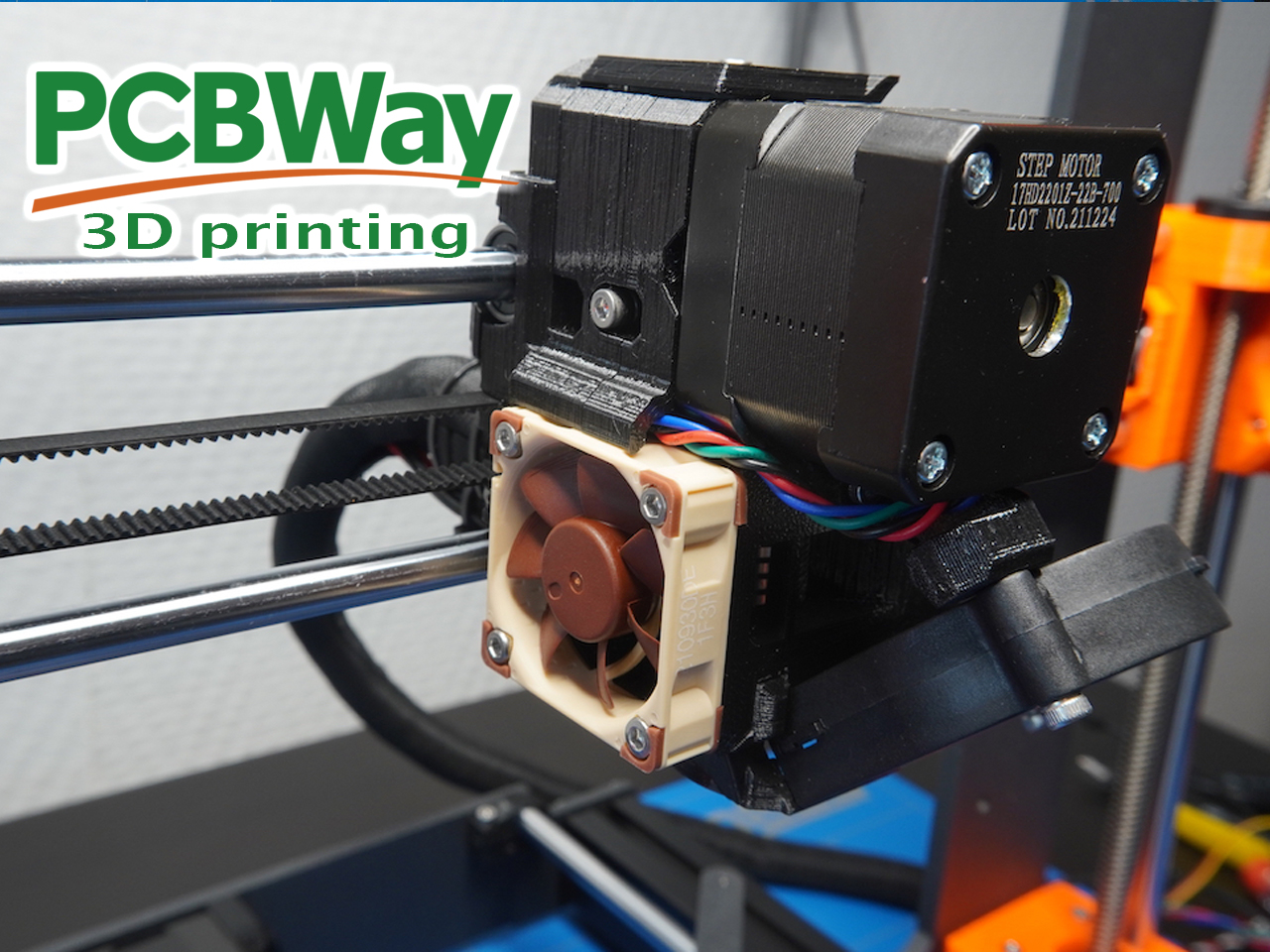
The extruder is the heart of the 3D printer. It spews filament at the correct temperate through the heated nozzle.
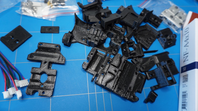
I have started with 3D printing all of the required extruder parts using black PETG filament, except for the fan-shroud part which is using ASA filament. They can be found in the E-axis section of this i3 MK3S+ printable parts page.
PCBWay kindly offered to sponsor this 3D printer build. Next to PCB manufacturing and assembly services they also offer 3D printing services in various printing technologies like FDM, SLA, SLS, MJF, DMLS and Polyjet.
Initially, I thought that I would get away by using all of the cloned E3D V6 extruder parts and I did come a long way,
but after the full assembly I didn't like the way the thermistor was in the way of the fan-shroud
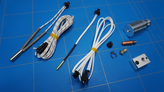
so I decided to get an original full metal 24V - E3D V6 Prusa extruder which comes with Semitec 104NT thermistor. This will also give me less hassle later while installing the original Prusa firmware later on.
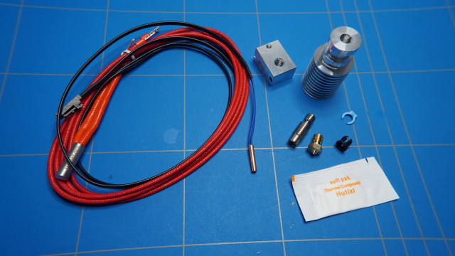
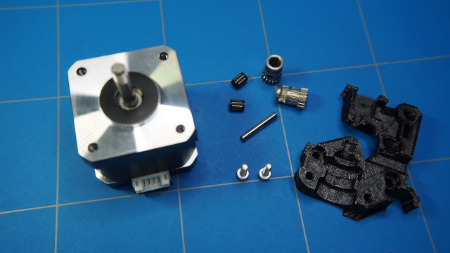
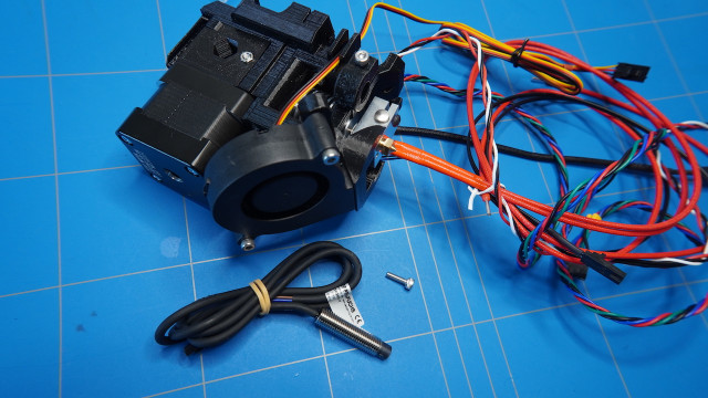
The unassembled version of the extruder consists of these parts:
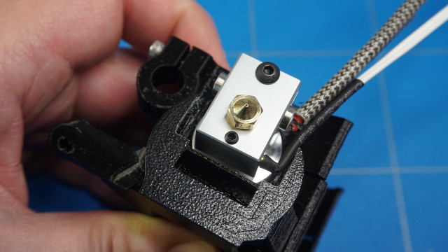
To assemble the extruder first, screw the nozzle all the way into the heater block.
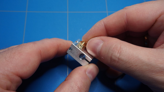
Then unscrew it one full turn.
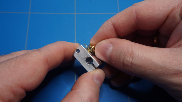
Next, screw the heat break all the way into the heater block.
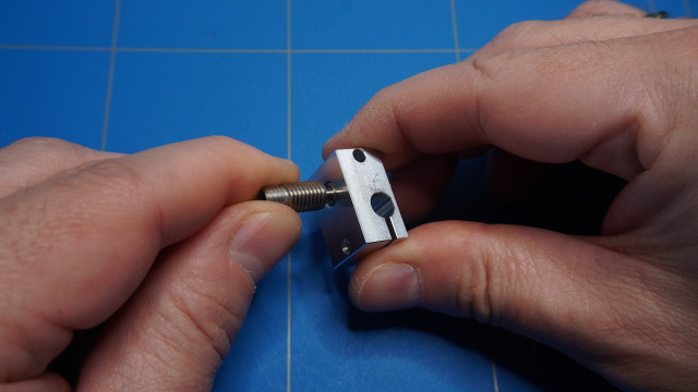
Apply the thermal compound to the windings of the heat break.
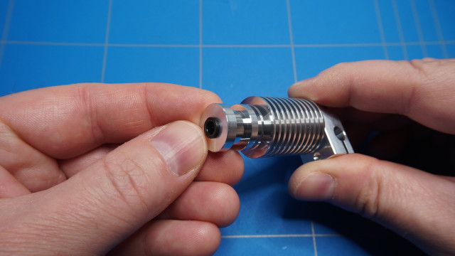
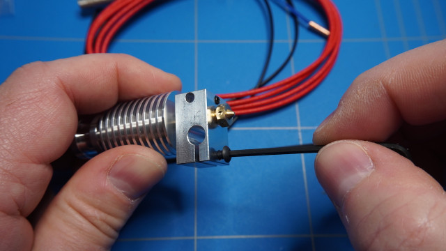
Screw the heatsink onto the heat break.
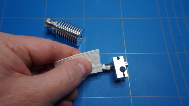
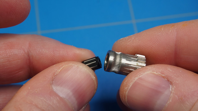
Insert the small black collet.
Then, insert the small PTFE tube.
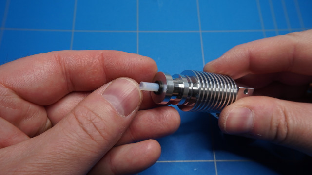
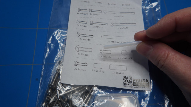
This tube can be found inside the MK3S fasteners spare bag, which can be bought in the Prusa webshop or if you have a PTFE tube with the dimensions OD:4mm ID:2mm you can also cut one yourself.
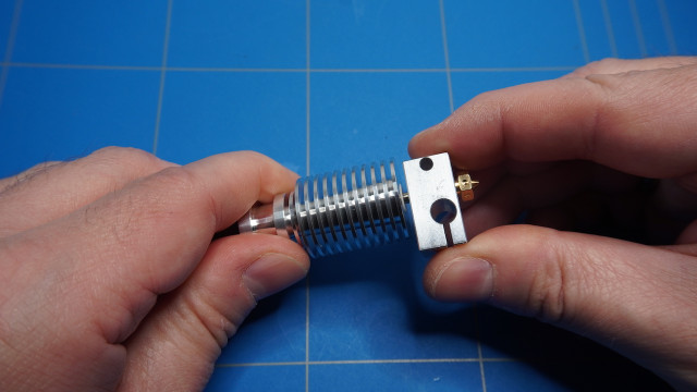
Prepare the heater cartridge and thermistor together with provided screws and Allen keys.

Tighten the screws lightly to the heater block.
Then insert the heater cartridge, make sure it is aligned in the middle and tighten the screw.
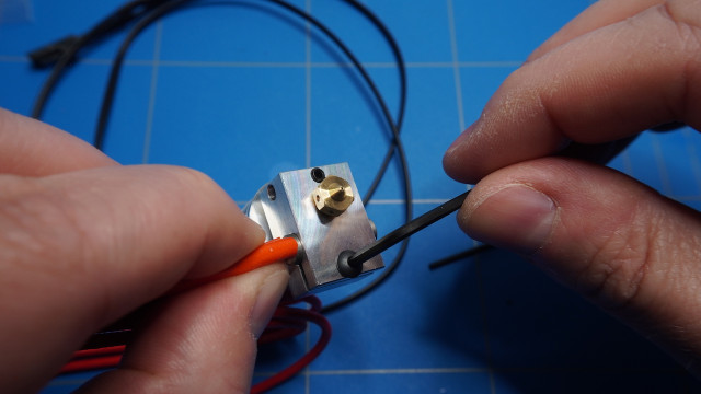
Do the same with the thermister.
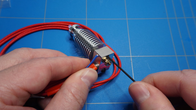
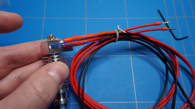
And we are done building the extruder. Tighten the cables together, so they will be not in the way during the rest of the assembly.
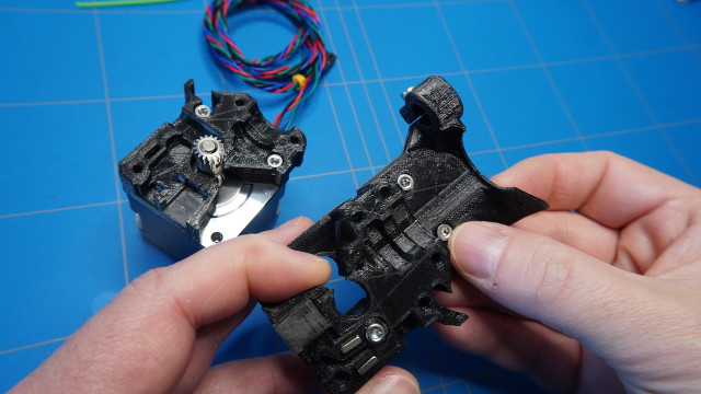
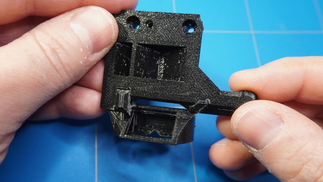
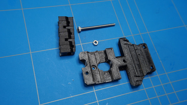
Prepare the 3D printed parts: extruder-body, adapter-printer and fs-lever.
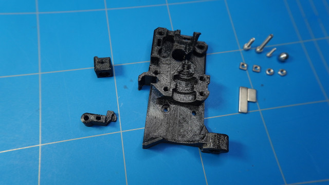
You will also need the filament sensor with cable, neodymium magnets, a small steel ball, 2x M3 hex nuts, 2x M3 square nuts, M3x18 and M3x10 screws. All of these parts are provided within this set that can be bought on the Aliexpress website. The magnets and the steel ball are also part of the spare parts bag that I mentioned before.
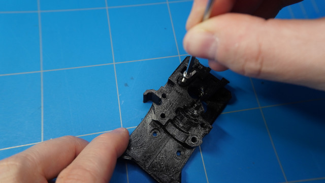
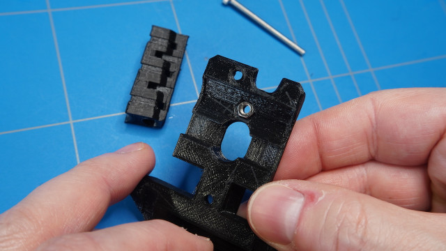
Start by inserting the M3 hex nuts into the extruder body part. You can use an M3 screw to pull the nuts inside the holes.
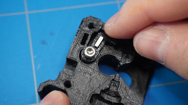
Then insert both of the M3 nuts.
The second square nut will hold the proximity sensor in place
using this M3x10 screw.
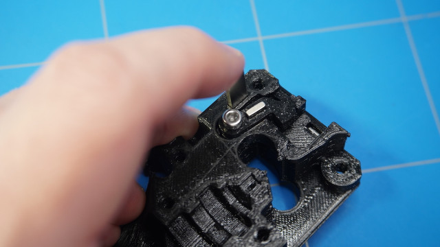
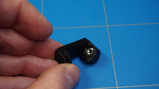
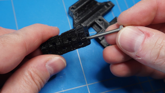
Then insert the smaller neodymium magnet into the fs-lever 3D printed part
amd place the part inside the extruder body and fasten it using the M3x18 screw.
The part should be able to move freely.
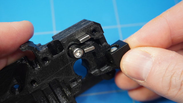
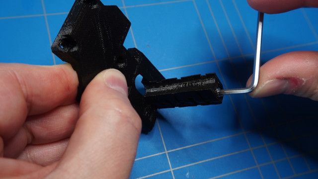
Insert the second magnet in a way that the 2 magnets will repel each other.
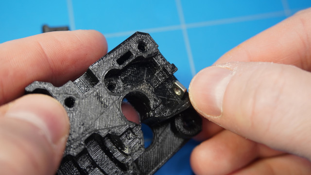
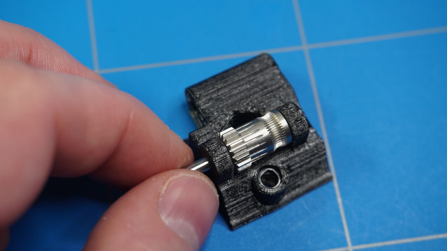
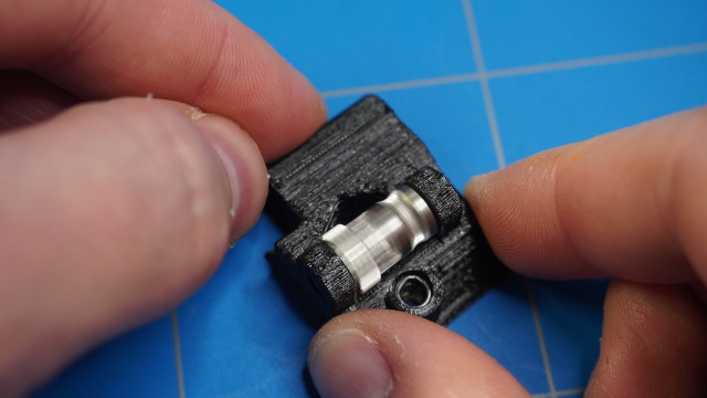
Now insert the small steel ball inside the adapter-printer part and slide it into the extruder body like in the picture.
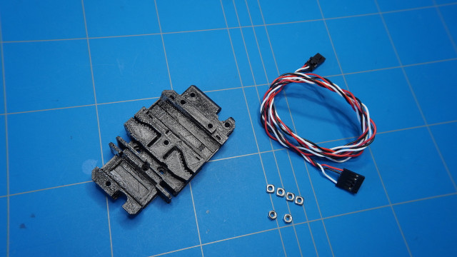
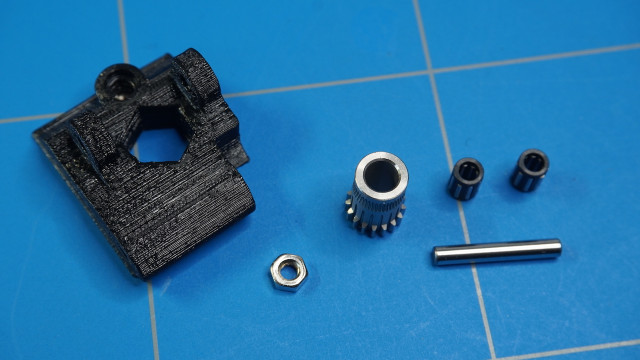
Prepare the following parts: 3D printed extruder-motor-plate, Btech gear set and the E-axis stepper motor. Note that I first tried to use a stepper motor with a plastic connector, but it would not fit within the assembly and I had to change it to one from this Prusa clone stepper motor set.
Fasten the extruder-motor-plate to the extruder motor using 2x M3x10 screws.
Fasten one of the BTech gears to the stepper motor shaft in a way that the filament will be able to grab it with its teeth.
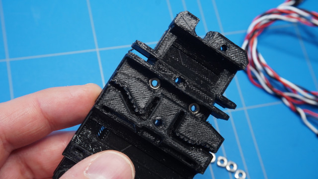
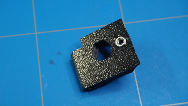
Prepare extruder-cover and insert the M3 square nut into the part.
Insert 2x M3x10 screws into the holes of the extruder-body part.
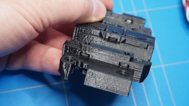
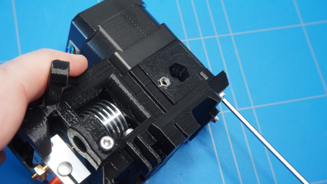
Then take the assembled extruder and place it inside the extruder body.
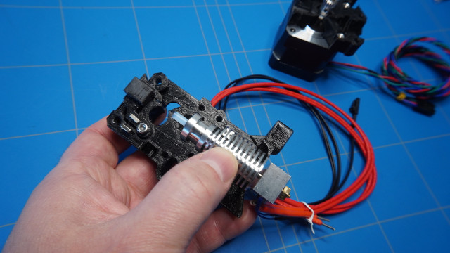
And place the extruder motor assembly on top of it.
.
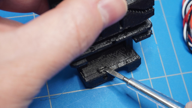
Using 2x M3x40 fasten the two parts together. Note that the screws will stick out of the assembled body, that is ok.
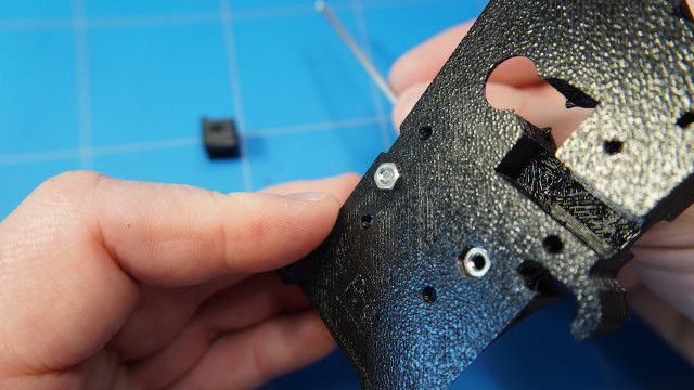
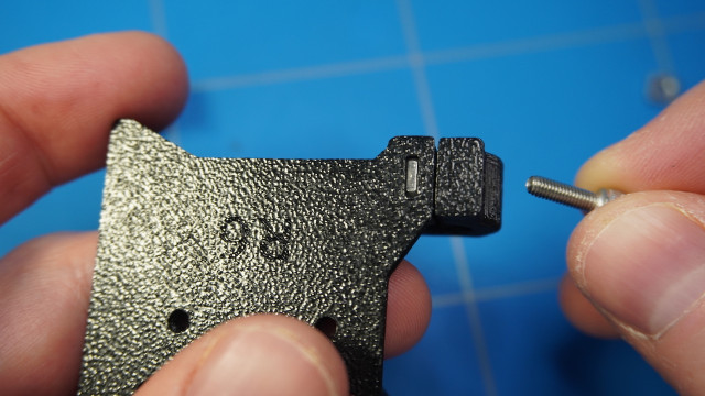
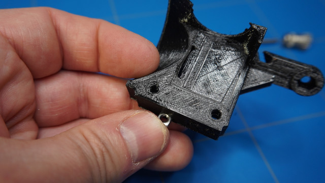
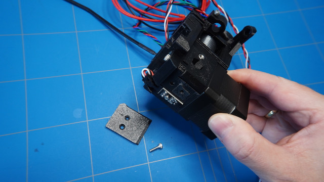
Prepare the 3D printed x-carriage part with 4x M3 square nuts, 2x M3 hex nuts and the filament sensor cable.
Insert the two M3 hex nuts into the designated holes. Use the screw pulling technique if needed.
Insert three of the M3 square nuts like in the picture.
And the last one here.
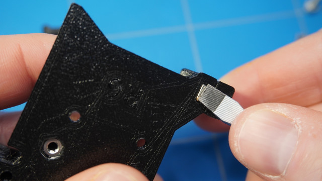
Place the filament sensor cable inside the groove of the x-carriage part. Make sure that the connector is sticking out about 15 mm.
Guide the extruder cable like in the picture below and align the x-carriage part to the screws of the other part.
Close it up using the already inserted M3x10 screws.

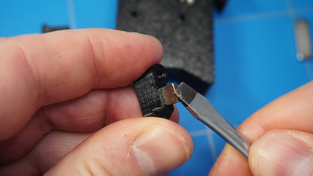
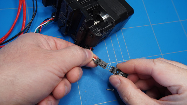
Attach the filament sensor. Note the orientation! GND wire is black.
Put it on top and fasten it tight using the M2x8 screw.
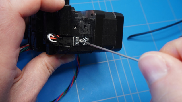
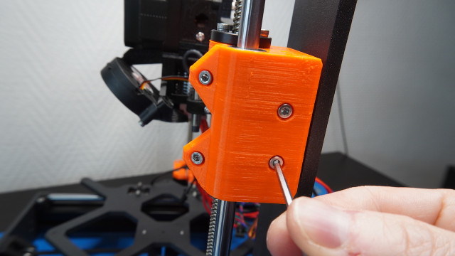
Fasten the assembly by using an M3x40.
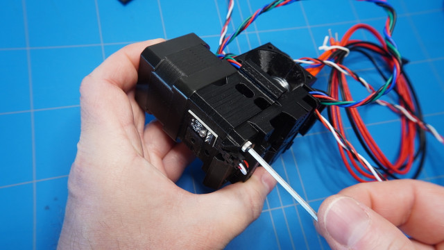
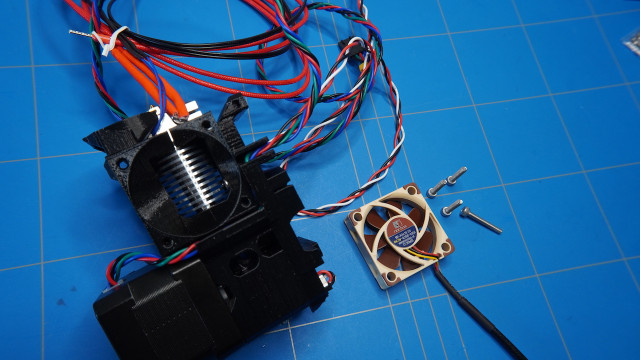
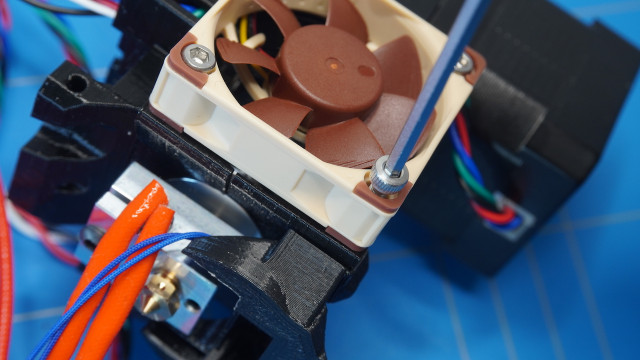
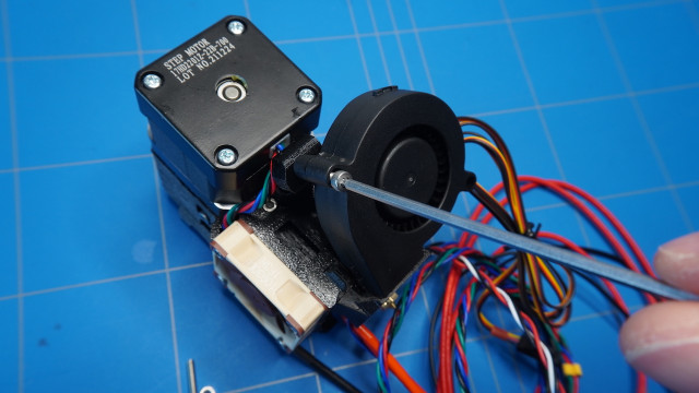
To cool the extruder I have used this Noctura NF-A4x10 5V fan. It has a 3-pin connection, which is the same as the one that is used by Prusa. Also, prepare 3x M3x16 screws and an M3x20 screw.
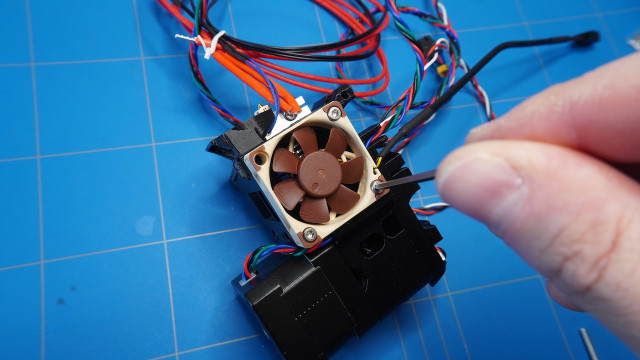
Fasten the 3x M3x16 screws, but leave the last one.
Insert an M3 square nut into the fan-shroud part.
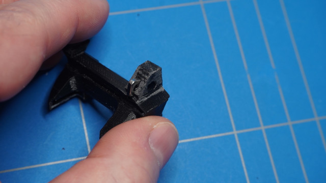
Also, don't forget to remove the support from it.

Then slide it onto the bottom of the assembly.
And finally, fasten it with the M3x20 screw.
Gather the rest of the BTech gear set together with the 3D printed extruder-idler part.
Insert an M3 hex nut into the extruder-idler part.
Assemble the gear by putting both bearings inside the pulley.
Insert the shaft into the idler part
and make sure it rotates freely.
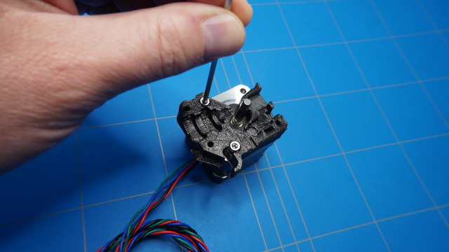
Place the assembled extruder idler into the assembly and fasten it using an M3x40 screw.
Find the fs-cover part together with an M3x10 screw
and put it on top of the IR filament sensor.
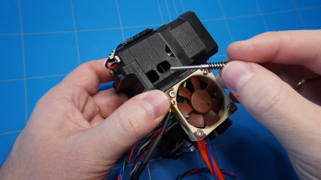
Use an M3x40 with a spring to add tension to the idler. The partly threaded screw and the spring are a part of the MK3S fasteners spare bag. You can also get the extruder spring with the following specifications:
Length: 15mm
Wire diameter 0.8mm
Outer diameter: 0.5mm
To connect the print fan gather the print-fan-support part, M3 hex nut and an M3x10 screw.
Insert the M3 hex nut inside the plastic part.
And fasten it to the assembly.
I have ordered the original 5015 5V print fan in the Prusa shop as I thought that it would be of better quality than the ones found on Aliexpress. But I don't know, maybe they are of similar quality.
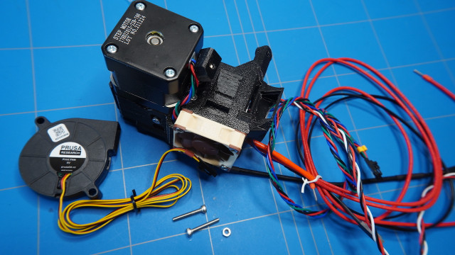
You will also need 2x M3x20 screws and an M3 square nut to attach it.
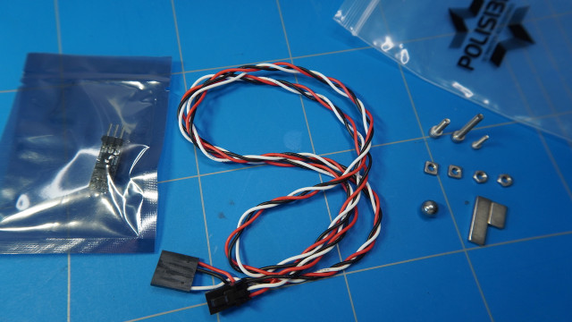
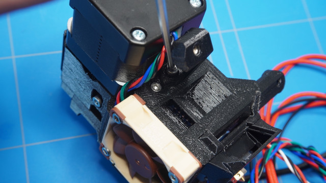
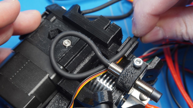
We can now proceed to the assembly of the proximity sensor. This sensor is called Super PINDA by Prusa. I bought the original as well, just to avoid some problems with clones. I did order one on Aliexpress but haven't tried it to really see the difference.
Insert the sensor into the holder and lead the wires as shown in the picture. At this point, the exact placement does not matter. The sensor will be calibrated at the end of the build.
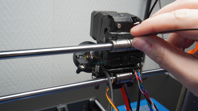
Next, insert two zip ties into the holes in the back of the assembled extruder.
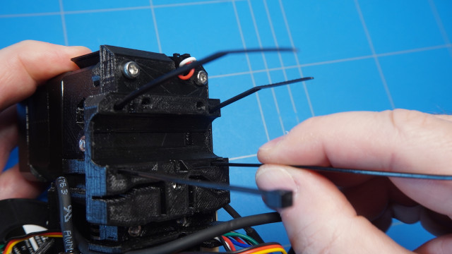
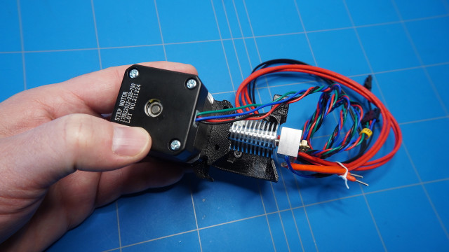
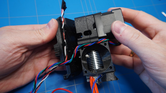
At this point, you should have a fully assembled extruder with a lot of wires sticking out of it.
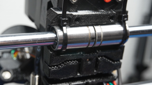
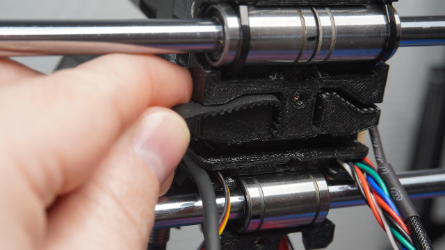
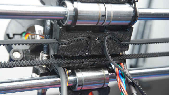
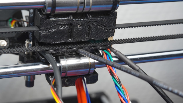
Fasten the zip ties onto the linear bearings of the x-axis. Make sure that the cables are leading out like in the picture. Cable management is an important part of the Prusa printer build.
They should look like this. You can now cut off the parts of the zip ties sticking out.
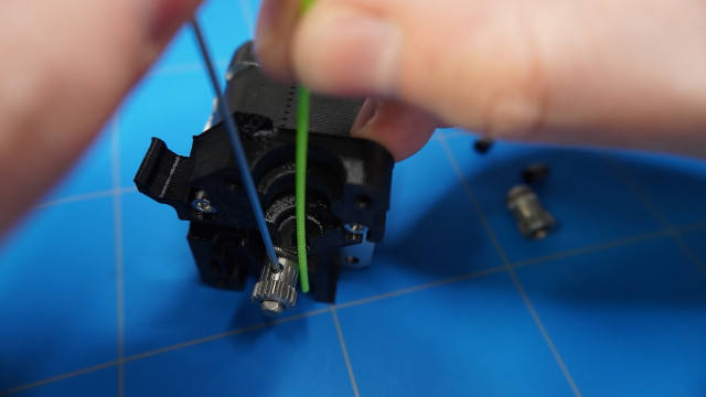
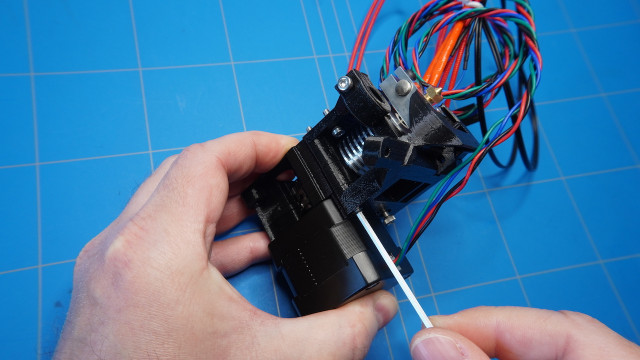
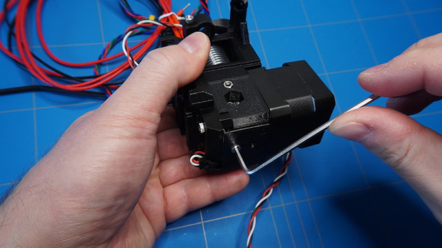
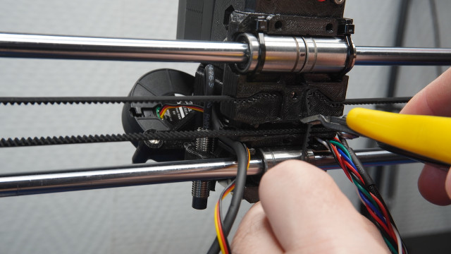
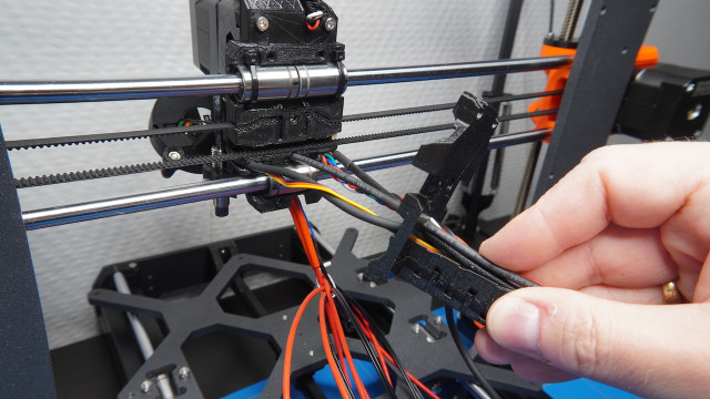
It is time to connect the 6mm GT2 timing belt to the assembled extruder. The length of the X-axis belt is 850 mm. First, insert the end of the cable into the groove.
Then lead it to the side through the idler roller.
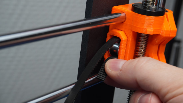
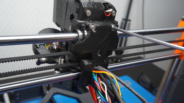
Back to the other side where the GT2 16 teeth timing belt pulley is located.
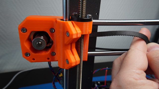
And finally back to the groove on the back of the x-carriage. Pull the belt as tight as you can, but don't overstretch it.
If the belt is too loose you can adjust it with the screws on the x-end-idler.
When you are happy about the tension you can cut off the remaining part of the belt. The belt tension is also a part of the calibration process, so don't worry about it at this point of the build.
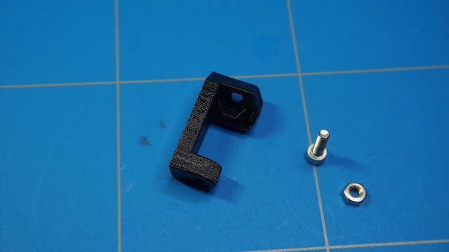
To complete the cable management of the extruder we will start by setting aside the x-carriage-back and the cable-holder 3D printed parts. You will also need an M3x40 screw and an M3 hex nut.
Slip the M3 hex nut into the designated hole in the x-carriage-back part.
Next, insert the M3x40 screw into the cable-holder.
Assemble the two parts together.
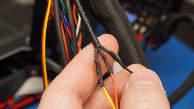
The original Prusa uses a 2.75mm nylon filament as support for the wires, but I didn't have that and used a 1.75 PETG filament instead and wrapped it around a 3mm shrink tubing. I might replace it later, but it will have to do for now.

Then it can be inserted into the hole that is sticking out of the x-carriage part.
Lead all of the cables, except the hotend and thermistor wire, through the hole of the x-carriage-back part.
And fasten it using 4x M3x10 screws.
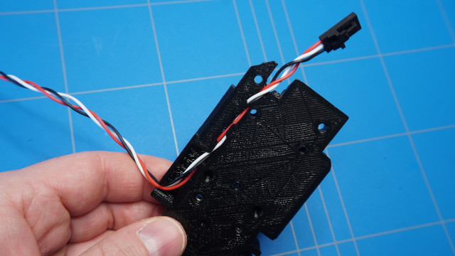
I have also cut off the end of the Noctura fan connector and connected extension wires to it.
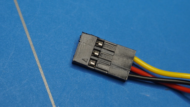
On the end of it, I have added a 3-pin Dupont connector. Note that the colours need to be arranged as in the picture below.
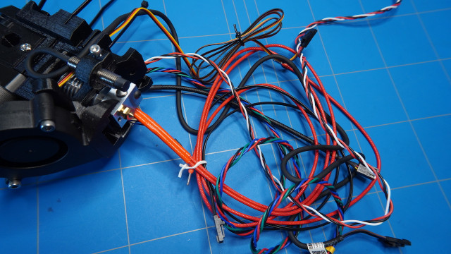
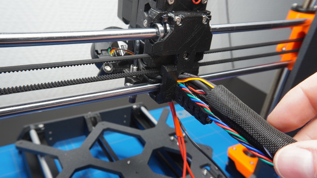
Then insert all of the wires into a 50 cm long textile sleeve with a diameter of 13mm.
And fastened them using tie wraps.
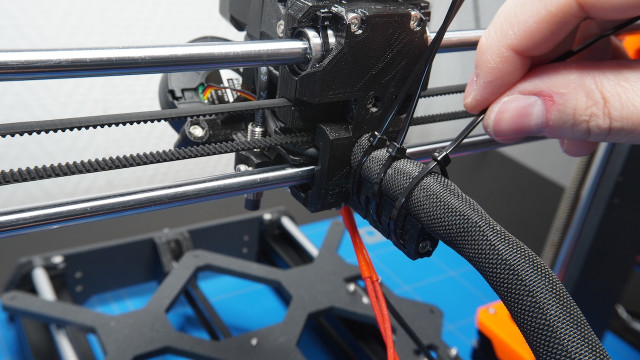
Do the same to the hotend and thermister cable on the bottom of the cable-holder.
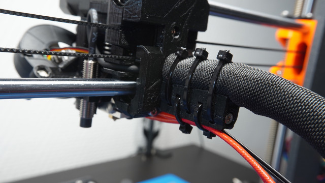
And you are done! I have to say that this was the most time consuming and complicated part of the 3D printer build, but it was very rewarding to see the finished extruder that is ready to print some nice 3D objects.