The X and Z axes are intertwined together and it is a good idea to assemble them in one session.
I have decided not to use original parts for the X-axis assembly and I thought that the X-Axis revision with a belt tensioner is better. In my previous 3D printer build I have noticed that the X-axis belt loses tension after a while and it is a good idea to have a system that lets you adjust it easily. This version replaces the original files x-end-motor.stl and x-end-idler.stl.
PCBWay kindly offered to sponsor this 3D printer build. Next to PCB manufacturing and assembly services they also offer 3D printing services in various printing technologies like FDM, SLA, SLS, MJF, DMLS and Polyjet.
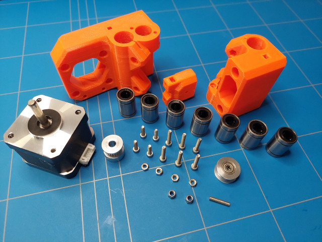
The parts that you will need to assemble the X-axis revision are:
- 3D printed parts in PETG. I have used the original Orange Prusament PETG from Prusa.
- LM8UU Linear bearing (7x)
- M3x12 screw (4x) used for bearing clamps.
- M3 Hex nut (4x) is also used for bearing clamps.
- M3x18 screw (4x) to attach the stepper motor.
- M3x20 screw (2x) for belt tensioner and
- M3 Nylock nut (2x) for belt tensioner.
- GT2 Timing Belt Pulley 16 teeth, 5mm Bore and 6 mm belt width
- M3 or M2.5 14mm Dowel Pin. In my case, I have cut off the M3x40 screw as I found that the dowel pin was a bit too tight to insert into the roller bearing pulley. Maybe a better solution is to use an M2.5mm version of the dowel pin.
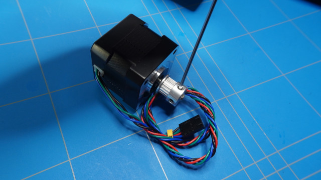
- X-axis stepper motor from the Prusa clone stepper motor set. The one in the picture below is from my initial purchase, but as I already mentioned in the previous post I have replaced it.
First, slide all of the LM8UU linear bearings into the X-end pieces.
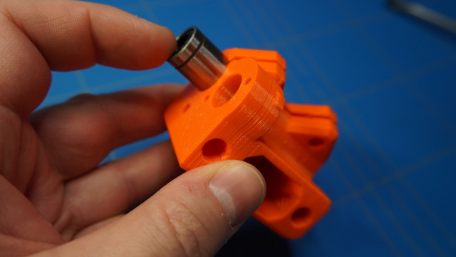
Try to align them so the balls inside will be in a cross setting like in the picture below.

Insert the M3 hex nuts (4x) into the designated holes.

And tighten the linear bearings using the M3x12 screws (4x).
Side the GT2 Timing Belt Pulley on the shaft (make sure the orientation is like in the picture) and fasten it. Don't worry about the exact position as we will adjust that later.
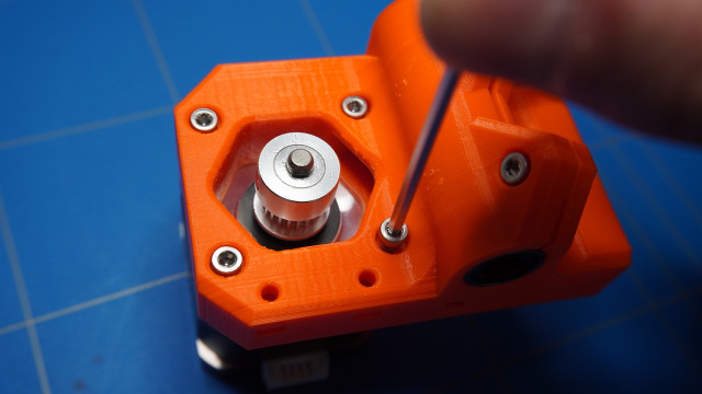
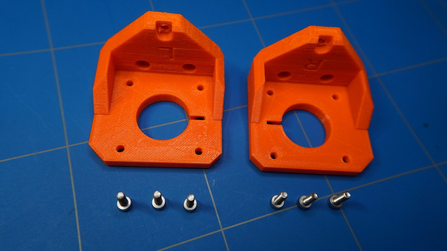
The next step is to attach the stepper motor to the X-motor part using M3x18 screws (4x).
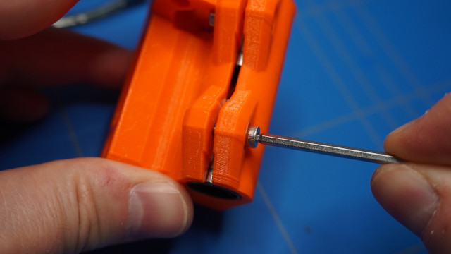
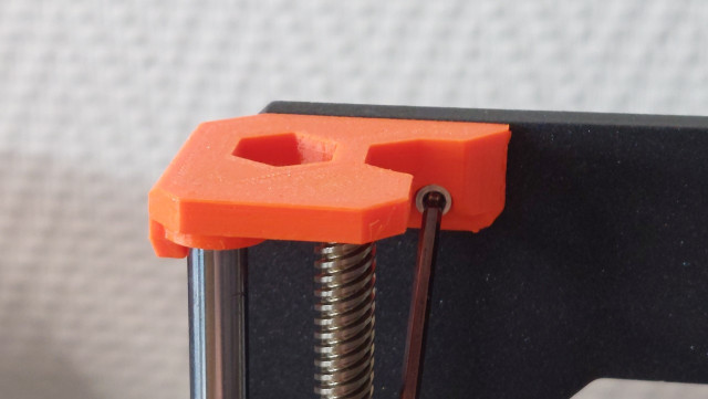
Then I inserted both M3 nylock nuts into the x-end_tensioner 3D printed part.
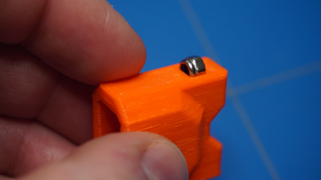
And attach the two M3x20 screws.
The roller bearing pulley slides inside that part and the M3 (or M2.5) 14mm dowel pin locks it in place.
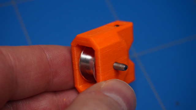
It slides right into the x-end-idler part.

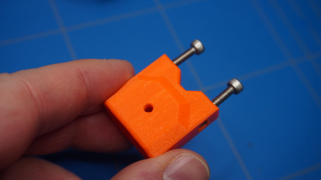
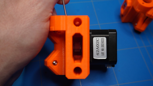
But.. after trying to fasten the M3x18 screws, one of the screws started to spin around inside the hole and I had to remove it.
So I have redesigned the x-end-tensioner part that uses M3 square nuts instead of the nylock nuts.

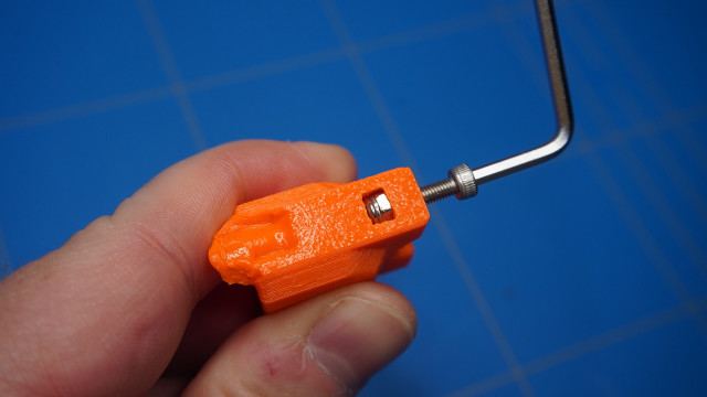
To align the GT2 timing belt pulley you can check if it is centred and fasten it using a hex key.
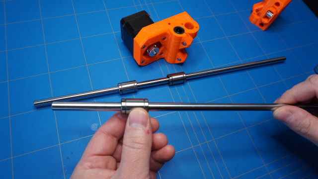
Now use a sharpie to mark the linear bearings.
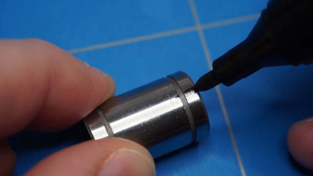
Do it in a way that the marking is between the two rows of balls.

Select the longest set of rods (370 mm) and set aside the remaining 3 linear bearings.

Slide the bearings onto the rods
I have predrilled the 8mm holes on the x-end parts.
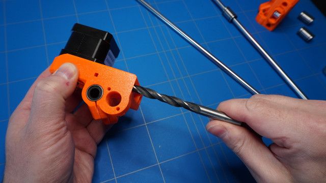
So the rods will slide in with less friction.
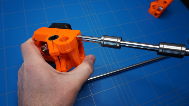
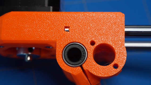
Finish the X-axis by pushing both rods into the x-ends. Make sure the rods are all the way through by checking the small window in the plastic x-end parts.
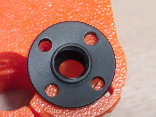
Prepare the following parts:
- T8 Nut (2x). These nuts are also included in the Prusa clone stepper motor set
The specifications of these nuts are represented in the picture below.
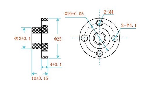
Please note that there are various sizes of these nuts. Initially, I bought the wrong ones and they were too small. So beware!
You will also need:
- 3D printed parts (2x) z-axis-bottom, z-screw-cover and z-axis-top. I have printed the Z-screw-covers in black PETG and the other parts using orange PETG Prusament.
- M3x10 screw (18x)
- M3x18 screw (4x). To attach the T8 nuts.
- M3 Hex nut (4x)
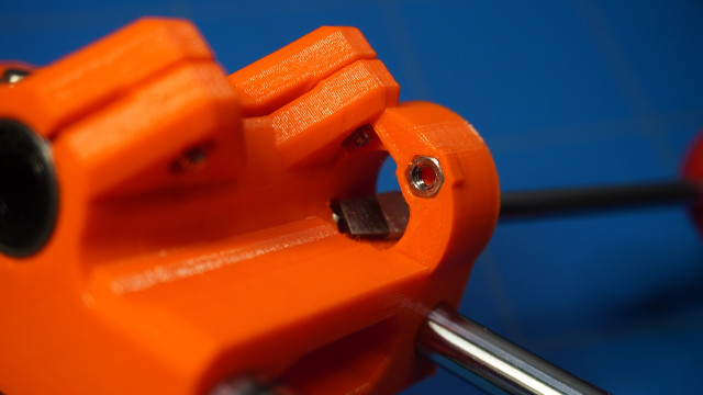
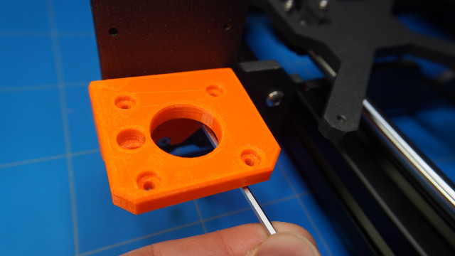
First, insert the M3 hex nuts inside the x-end parts.
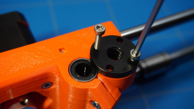
Fasten both T8 nuts.
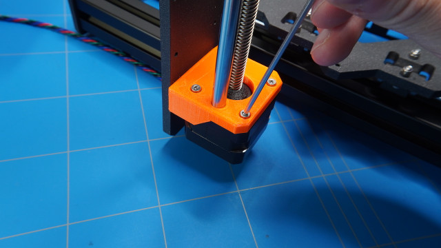
Prepare the z-axis-bottom parts and six M3x10 screws.
Attach them to the frame.
Then fasten the stepper motors using a total of eight M3x10 screws. Don't forget to add the z-screw-covers and you can also insert the 8mm smooth rods (320 mm).
Then you can slide the X-axis assembly onto the Z-axis rods. Be careful otherwise you can push out some of the balls from the linear bearings.
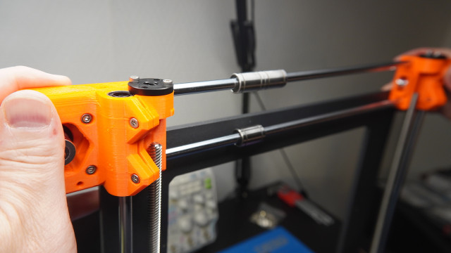
Finally, you can attach the z-axis-top parts using the remaining four M3x10 screws.
We are now finished with the build of the X and Z-axes. In the next part, we will focus on the extruder also known as the E-axis.