A while back I have assembled this bench power supply kit, which I received as a gift from my friend Eric. The kit was published in a Dutch electronics forum (Circuits online) as PCB Lab voeding. It was time to create a casing for it as it was just lying around in my drawer and was not really being used.
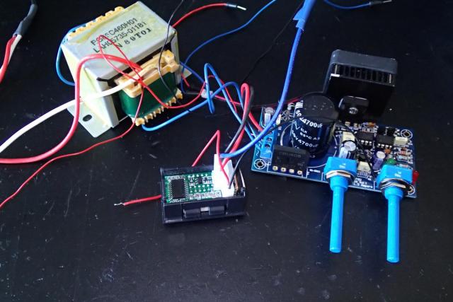
The kit was already working, but it was not very convenient to use. It also included a 24V 3A power supply and a voltage amp meter that I have bought in a Chinese webshop.
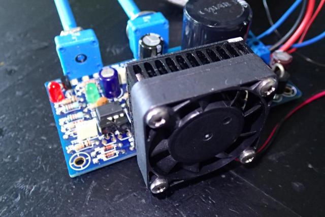
I have also added a heat sink and a fan to it.
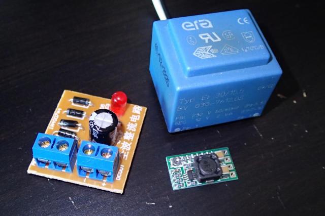
The manual of the kit has stated to use an extra transformer to power additional gadgets and meters, so I have added this 12V unit together with a rectifier board and an adjustable step down voltage regulator.
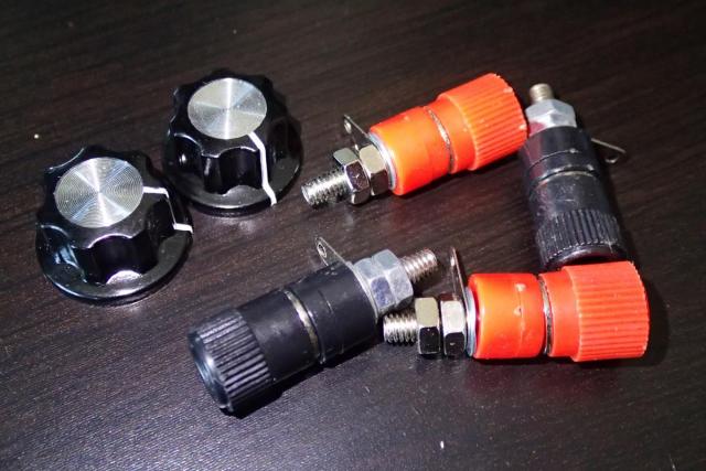
I also wanted to incorporate some banana plugs, potmeters knobs and other power switches into the design.
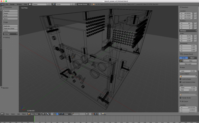
I have started a painful and time consuming process of designing the cover. Download here the finished lab power supply design.
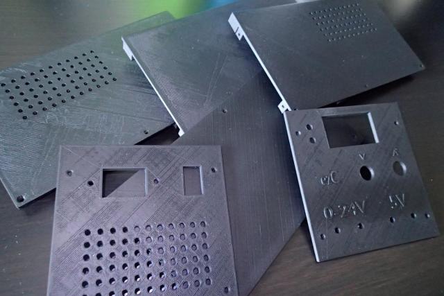
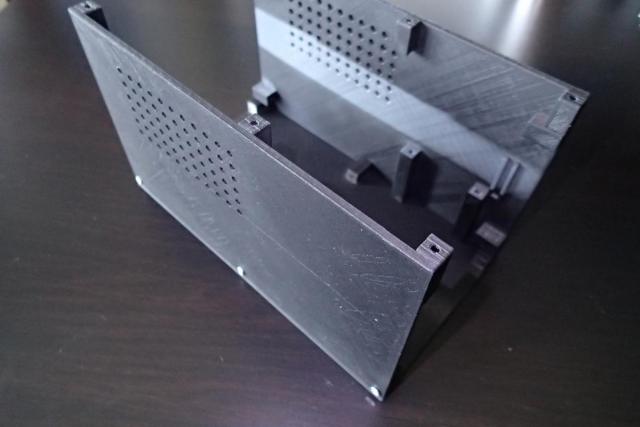
I was time to print it. For that I needed to split the design into parts because as a whole it would take over 6 days to print. I also did not have a lot of filament left, so I decided to print it in all colors that I had left and then spray it black. Notice that the front panel in the picture is not the one that I have ended up with.
First I have put together the bottom of the case and the sides.
Next I have desoldered the indicator leds.
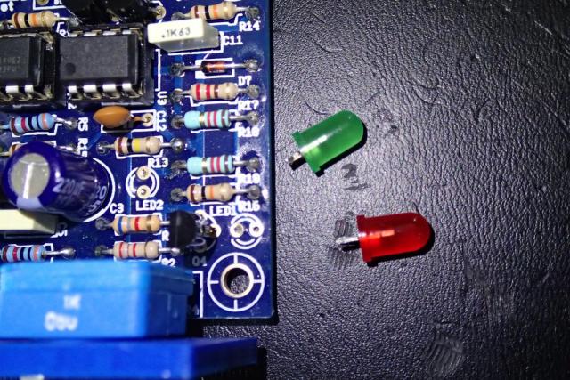
And soldered extension wires to them. In order to avoid short circuits, it's a good practice to add heat shrink tubing.
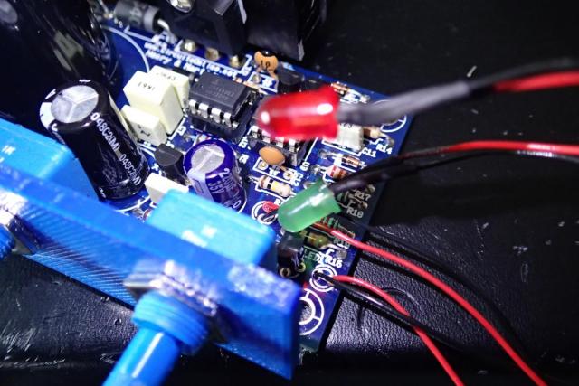
I did the same to the 12V transformer that will power the voltage/amp meter and the fan.
![]()
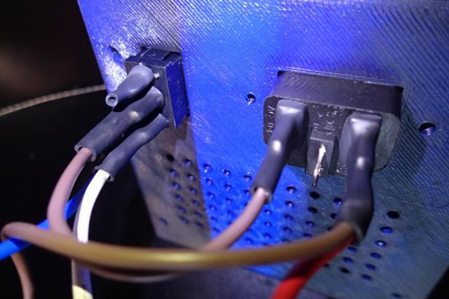
Then I have connected it, together with the 24V transformer to the C14 power plug and switch using terminal connectors. Note that the live (brown) wire is being switched.
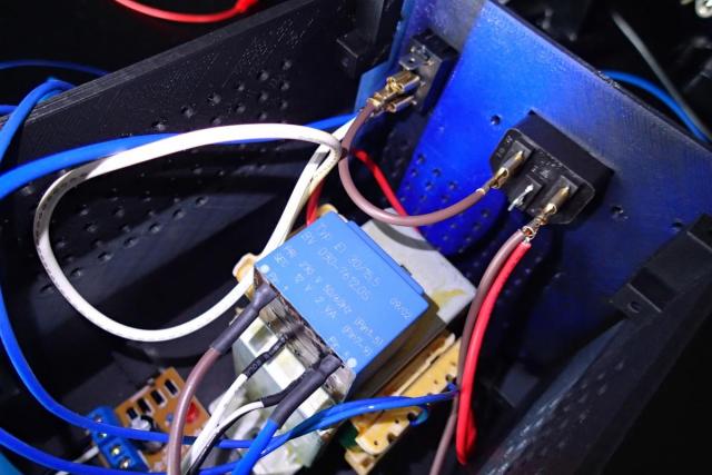
Just for safety reasons I also added heat shrink tubing on the power elements.
On the top of the 24V transformer I have attached the 12V transformer using an double sided adhesive tape.
![]()
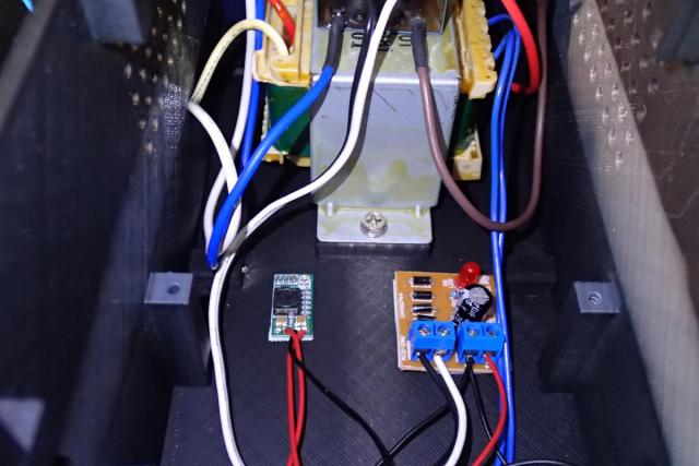
After that I have connected the AC output of the 12V transformer to the rectifier board and the DC output of that board into the adjustable step down voltage regulator to power the fan and voltage/amp meter.
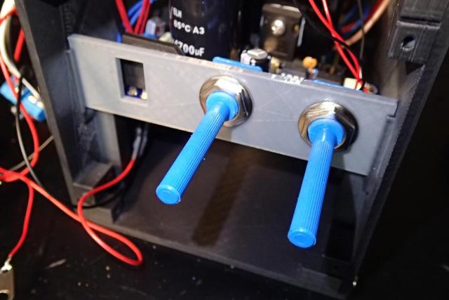
I could now add the PCB board inside the box and fasten the potentiometers onto this printed piece.
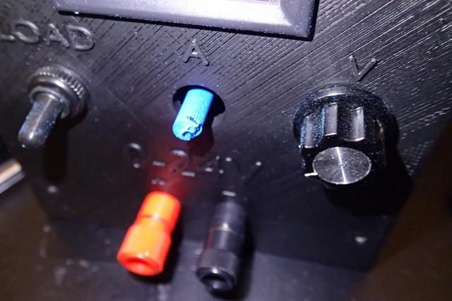
The I could attach all the wires to the banana plugs, load switch and the leds to the front panel.
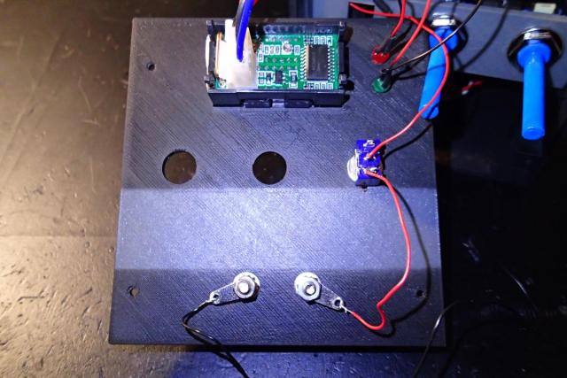
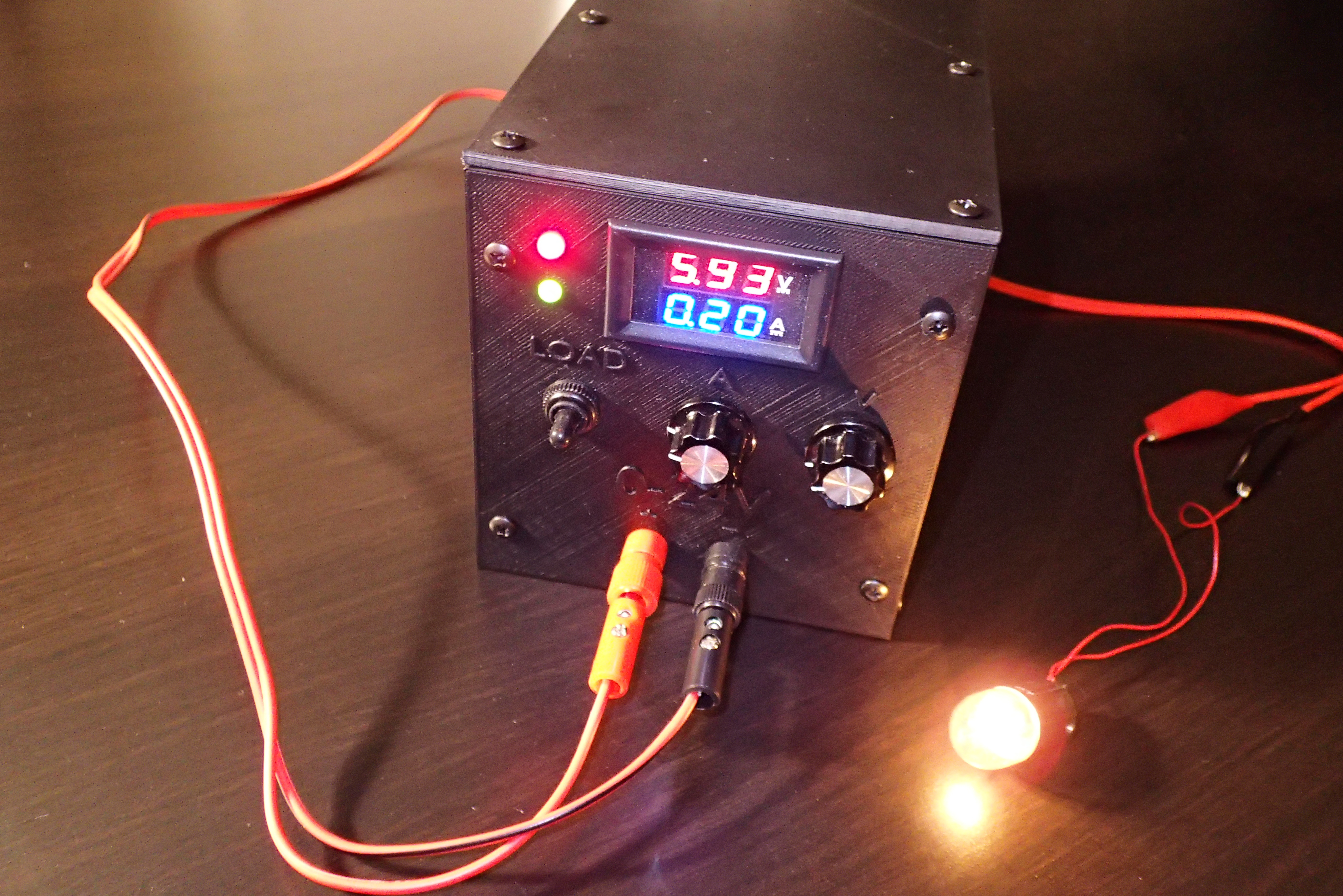
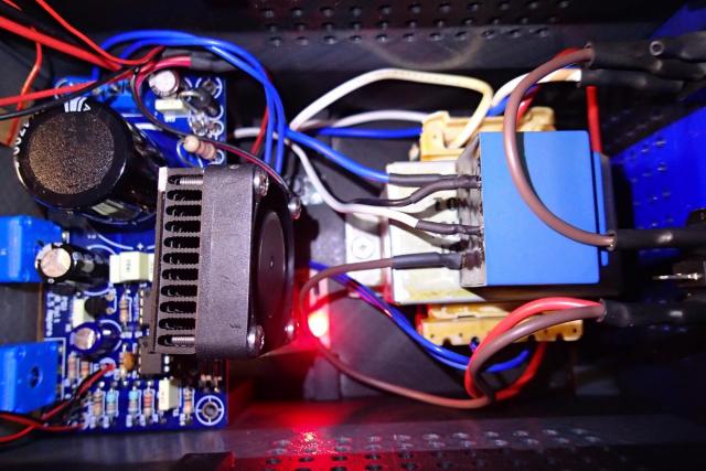
The insides of the lab power supply ended up looking like this.
To finish it up I had to cut off the long ends of the potmeters in order to install the knobs.