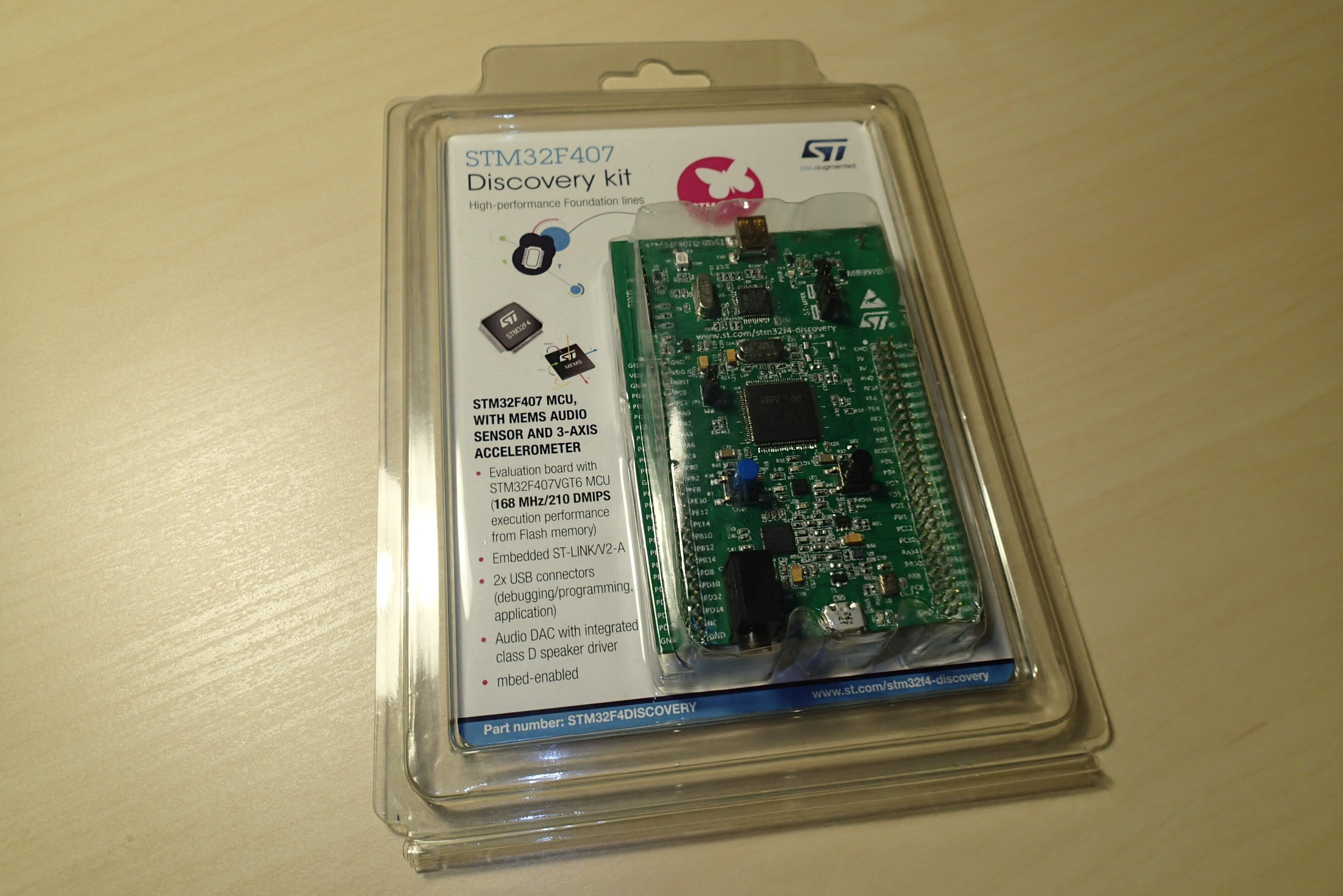
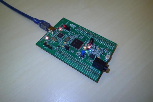
Blink LED is a Hello World! application for micro-controllers. If you manage to get it running, you can assume that you are all setup and ready for further developments on your board. In this blog item I will cover how to do that on a STM32F407 Discovery board.
The microprocessor that is present on this board is STMicroelectronics ARM STM32F407VGT6. There are also other ICs installed on this board for experimental development, like the MEMS audio sensor and 3-axis accelerometer. When you first turn of the board you can use the accelerometer as a mouse by simply connecting the microUSB port to your computer. But we are going to delete that demonstration app and create our own blink LED program.
To start we are going to download software that is needed for the board development. The first application is called STM32CubeMX and it will help in the creation of initialisation code for our Blink LED program. STM32CubeMX application can be downloaded on the st.com website. Scroll to the bottom of the page for the download link. Unfortunately you will need to register first.
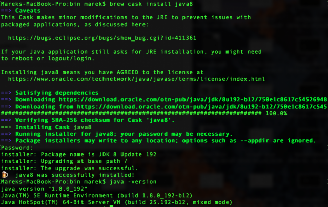
On my MacOS High Sierra I needed to install Java 8 JDK. It's easily done with brew (cask). The commands to do this is:
brew tap caskroom/versions
brew cask intall java8
First I have tried to install Java 11 JDK, but when executing the STM32CubeProgrammer it resulted in an error.
If previously the setup of STM32CubeMX didn't work, it should do now.
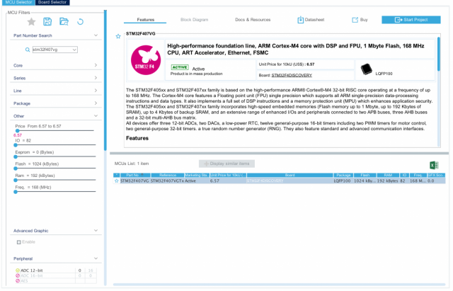
Start the STM32CubeMX application and select File -> New Project... You shall be presented with a MCU selector like in the screenshot below. Search forSTM32F407VG and select this chip.
On the STM32F407 Discovery board product page download the user manual.
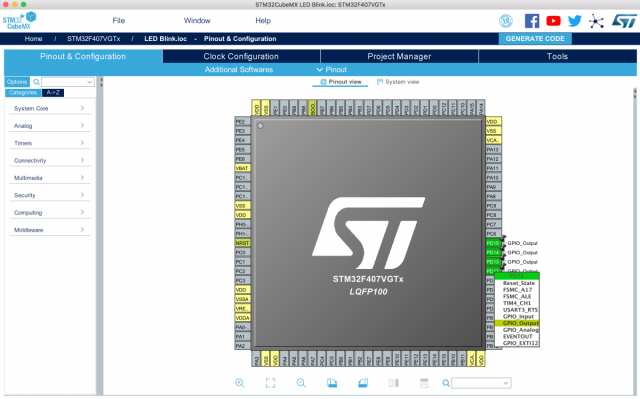
In the pinout configuration we need to choose the pins that are connected to the LEDs on the board. The User manual shows us that these are pins PD-12 .. 15.
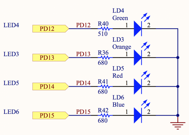
On the Pinout & Configuration tab mark them as GPIO_Output.
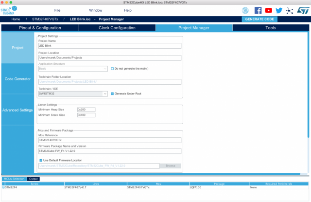
Leave the Clock Configuration tab as it is and on the Project Manager tab give the name to the project: LED Blink, select the folder and choose the Toolchain / IDE. In our case we will use System Workbench STM32 so we select SW4STM32.
As programming IDE for Mac OSX you can use System Workbench for STM32. The file that you download is called: install_sw4stm32_macos_64bits-v2.7.run In order to execute this script you first need to make it executable:
chmod +x install_sw4stm32_macos_64bits-v2.7.run
Install the application by running this script:
./install_sw4stm32_macos_64bits-v2.7.run
Installation goes smoothly. Somehow at the end of the install the script asks you to enter you system password. You will only notice that after the the installation wizard will get stuck and you accidentally go to your terminal screen.
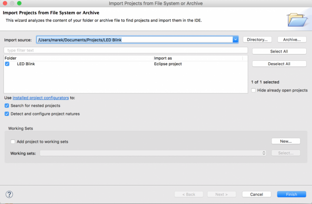
To open our Blink LED project go to File -> "Open Projects from File System..." Now you can browse for the folder where we generated our code with STM32CubeMX.
In the project, navigate to LED Blink/Src/main.c file. Locate the int main(void) function and add this code within the while(1) loop:
/* Infinite loop */
/* USER CODE BEGIN WHILE */

while (1)
{
  /* USER CODE END WHILE */

  /* USER CODE BEGIN 3 */
  HAL_GPIO_TogglePin(GPIOD, GPIO_PIN_12|GPIO_PIN_13|GPIO_PIN_14|GPIO_PIN_15);
  HAL_Delay(1000);
}
Build the project binary with Project -> Build All or press cmd-B on a Mac. Within the Debug folder you will find a file called: LED Blink.hex
Now we can program our board. From the list of avaiable STM32 programmers we can only find a couple that work on OSX. First we will use STSW-LINK007 to upgrade the firmware on our board. After you extract the zip excute the JAVA file STLinkUpgrade.jar.

Click on the button [Open in update mode] and Upgrade the firmware of your device.
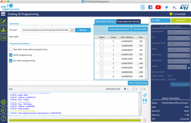
Now we will install STM32CubeProgrammer. After staring the application you can click on Open file and browse for the LED Blink.hex file. This will load the file into the application so you can see the contents of the file.Then connect to the device using the ST-LINK mode.
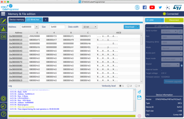
Inside the Erase and Programming section, browse for the LED Blink.hex file and click the Start Programming button. Optionally you can check Verify programming and/or Run after programming.
Your sketch is now uploaded to the board and the LEDs should start blinking.
If you wish to go back to the original board demonstration program, you can download this STM32F4DISCOVERY board firmware package. It also includes 22 examples (covering USB Host, audio, MEMS accelerometer and microphone).
The demo program is located inside:
STM32F4-Discovery_FW_V1.1.0/Project/Demonstration/Binary/STM32F4-Discovery_Demonstration_V1.0.0.hex
Follow the same instructions as above to flash this binary file onto your Discovery board.