Electrolytic capacitors are known for their terrible accuracy. Just by reading the value on the package is often not enough to know their true capacitance. In this blog I will show how to measure the real value by using a scope.
To determine the capacitance we will measure the time that it charges to a specific voltage. Using a simple circuit where a capacitor is in series with a resistor we can slowly charge a capacitor and measure the voltage across it using an oscilloscope. This circuit is also called a RC-circuit.
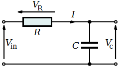
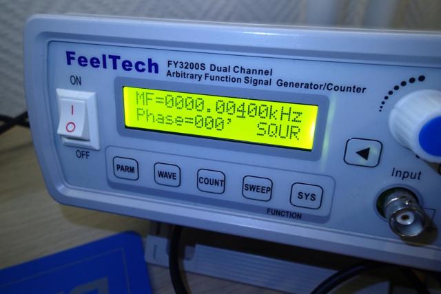
When we apply a voltage to Vin the capacitor will charge and when we pull Vin to ground it will immediately discharge. To achieve that, it is possible to use a block wave function generator that will oscillate between 0 and 5V at a specific frequency. This way we can charge and discharge the capacitor at a given rate. To calculate this rate we can simply multiply the values of the capacitor and resistor. In my case it is 100µF and 220 Ohm. The product of this will be a so called RC constant. At R * C seconds the capacitor will have charged till 63.2% of it's full potential. However the capacitor is almost fully charged at 5 * RC. So when we multiply 0.000100 F * 220 Ohm we get 22 ms. To determine the time when the capacitor will be fully charged we multiply 5 * 22 ms. It gives us 0.11 seconds. To calculate the frequency of our block wave we can take the reciprocal of it. 1 / 0.11 will then give 9.09 Hz. This number needs to be divided by 2 as the block wave drops from 5V to 0V after half of it's cycle.
Taking error margins in consideration, a 4 Hz block wave should fully charge and discharge our capacitor.
Completing our calculations we expect the voltage of our capacitor to be 3.16V (63.2% of 5V) after 22 ms. But will this be the case?
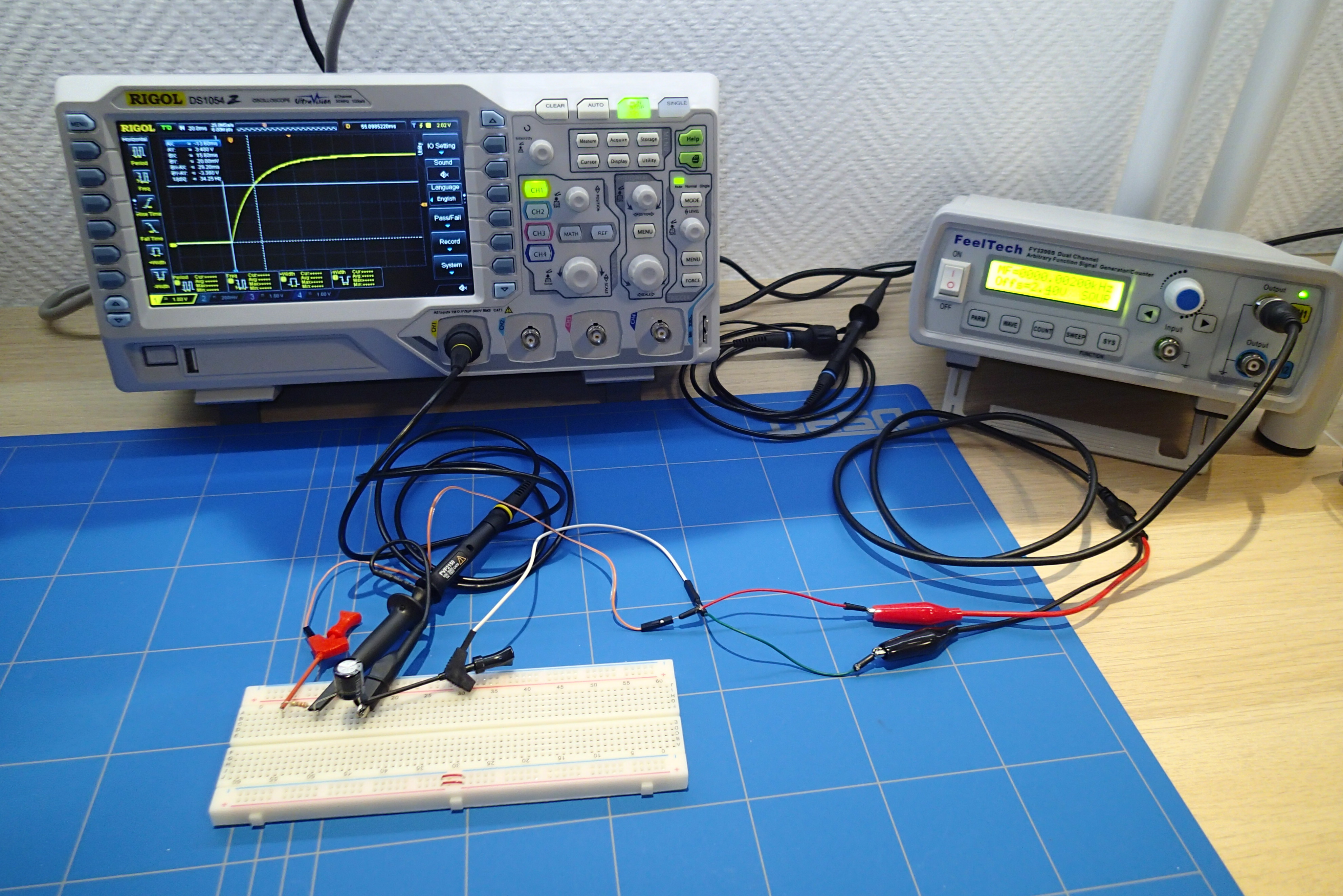
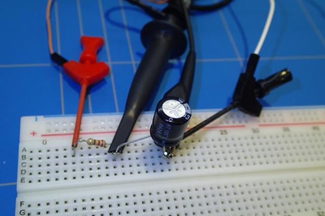
To build the circuit I have connected the function generator outputs across the resistor and capacitor. We take the measurement with the scope only across the capacitor.
This shows the following output on the oscilloscope. We set the horizontal cursors to the range of 3.16V and the vertical cursors to the beginning of the waveform and where the curve crosses the 3.16V mark.
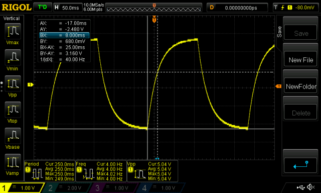
We read out 25 ms (BX-AX). That is a bit more then what we have calculated above. To be more precise I have also measured the value of the resistor as it had a 5% tolerance. The value of the resistor was 217.4 Ohms.

Taking into account the measured value of the resistor and the RC time that charged the capacitor to 63.2% we can calculate the true capacitance.
When we fill in the values for the derived formula C = t / R. C = 0.025 / 217.4 = 0.000115 F, which is 115µF.
The production error of our capacitor is 15%, which can be indeed called as terrible.
For the ones that are interested why the RC time constant is at 63.2%, I recommend reading this tutorial.