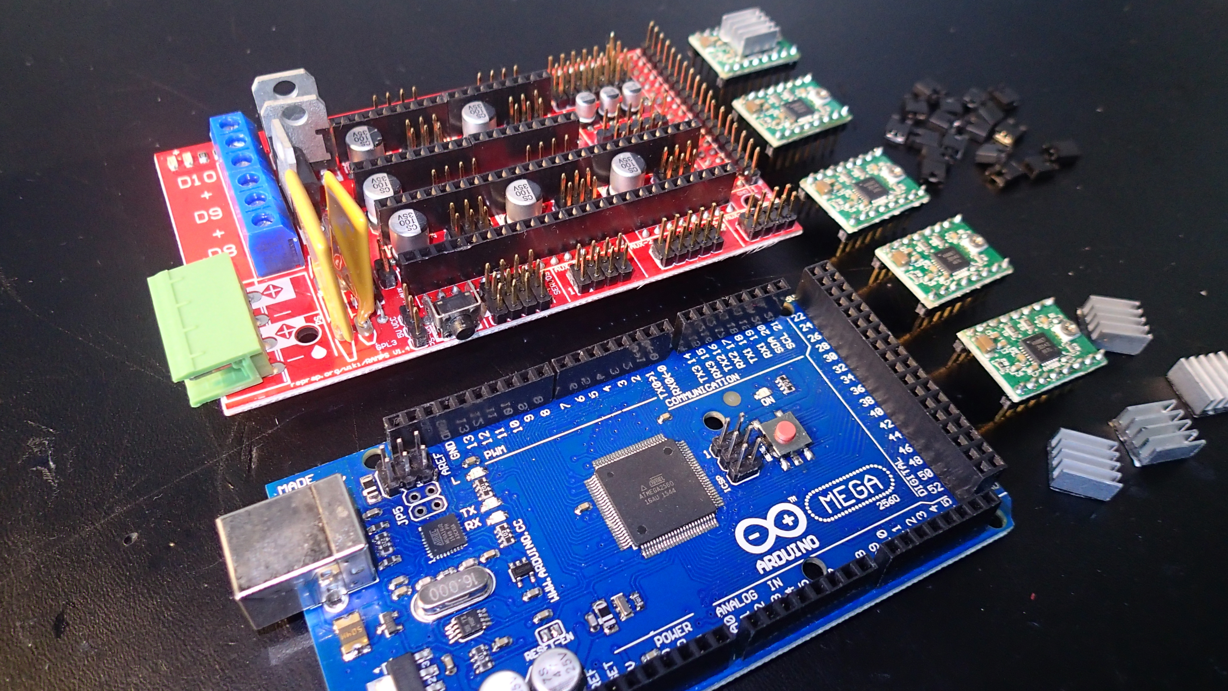
The brain of our 3D printer is the RAMPS 1.4 controller with Arduino MEGA 2560 board. In this part we will describe how to connect it to various components of our printer.
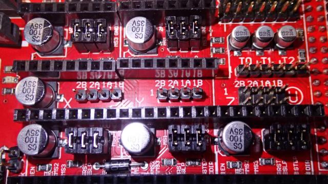
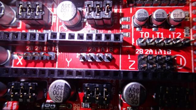
To start with we will need to build the complete controller. Beside the 2 boards mentioned above, we will need 15 jumpers and 5 pieces of A4988 stepper driver module. If you search for RAMPS 1.4 on eBay you can find compete packages that include all of the mentioned parts, but they are still not assembled. So, first place the jumpers on the RAMPS 1.4 board like this:
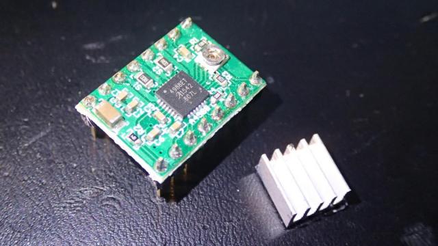
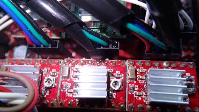
Next glue the heat sink on the chip of the modules.
The LCD 12864 board comes together with an attachment for the RAMPS 1.4 board.

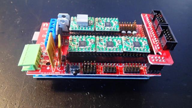
Now place the A4988 modules together with the LCD link part on the RAMPS board. Notice the position of the stepper driver module. The way that I remember it, is that the current adjusting "screw" needs to be on the right, on the opposite side of the power inputs.
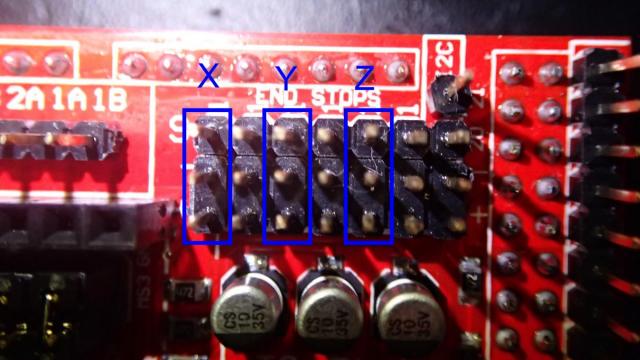
We are now ready to connect the stepper motors, endstops, thermistors, heatbed and extruder hotends. Initially we will connect the stepper motor outputs to the board. There are 5 sections on the RAMPS 1.4 controller. The bottom three ones are for the X, Y and Z axes and the other two are for the extruder stepper motors, named E0 and E1. First insert the connectors of X, Y and Z axes. Notice that the Z-axis has 2 outputs on the RAMPS board.
All the connections that we will make are based of this schematic overview.
This is how the stepper motors are connected to the board. The red wire is connects to 2B, blue goes to 2A, green to 1A and black connects to 1B.
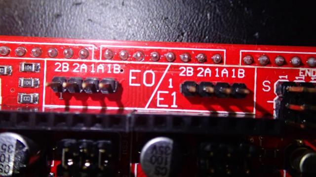
Do the same for E0 (extruder 1) and E1 (extruder 2) outputs.
The picture below shows connections with the correct color codes.
Now let's connect the 3 endstops. The connections are located in the top right corner and the silk screen layer provides good descriptions +/- which is obvious and S for signal. Our endstop boards have a led to indicate when the switch is active, so we will need all 3 pinouts to connect them.
Make sure the red wire connects to + and the green wire connects to the signal (S) input. (Notice the reversed view of the board in the picture below)
To hook up the thermistors locate the connectors to the right of the board with T0, T1 and T2.
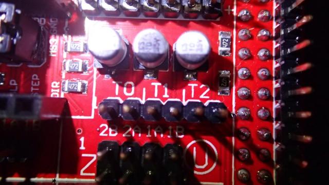
T0 connects to extruder 1 and T2 to extruder 2 thermistor. T1 is wired to the heatbed thermistor.
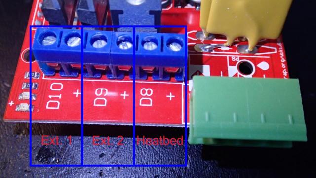
The hotends connect to D10 (for extruder 1) and D9 (for extruder 2). The heatbed connects to D8.
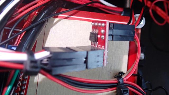
Because we are building a dual extrusion system, and usually the optional print fan is connected to D9 (which is actually the second extruder output), we will need addition output for this fan. This can be solved by adding RAMPS 1.4 RRD Fan Extender module.
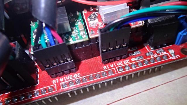
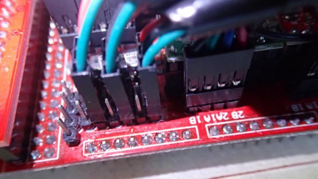
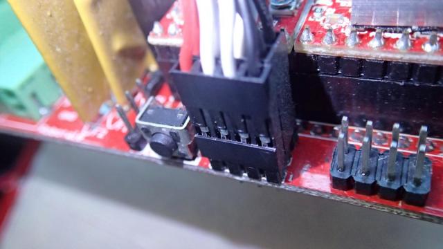
The place to connected to the RAMPS board is shown in the picture below.
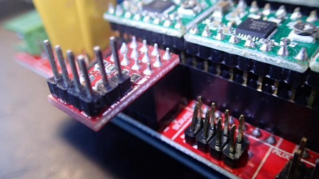
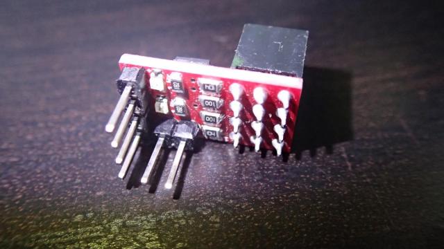
However, after we attach the board to the aluminum frame it will collide with one of the Z-axis stepper motors, so we will need to extend it with jumper connectors and some wire. I have combined 3x 4 pin output jumper connectors (female) and placed them on the board.
On the other end there are the opposite (male) connectors that connect to the RAMPS 1.4 RRD module.
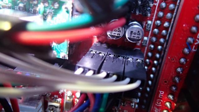
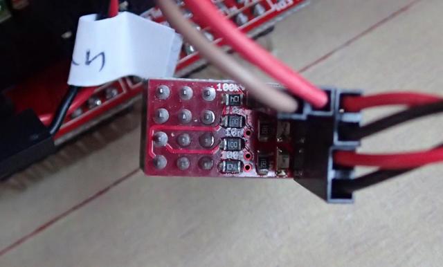
On the opposite side of the RRD board there is a power input and 2 fans outputs. The red/brown wires (horizontal position) lead to the RAMPS board where they connect to the extruder fan. The red/black wired connectors (vertical position) are for the fans. Top one is for the extruder fan and the bottom one is the print fan, that will blowing on the 3D print to cool it. The fans will turn on and off when needed. It will be covered in the next parts of this blog series.
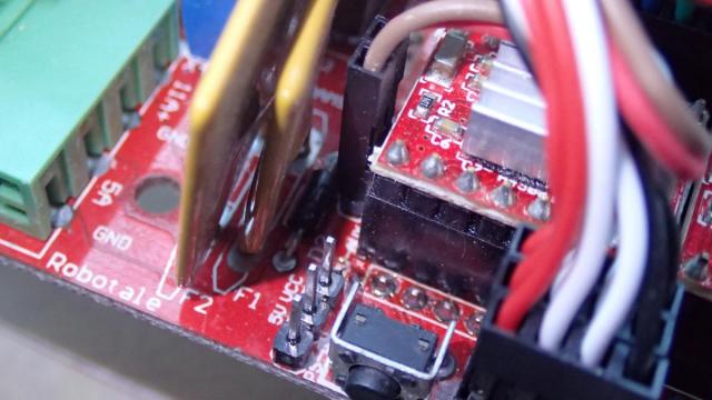
The extruder fan pinout on the RAMPS board are located to the left of the X-axis stepper motor outputs. Notice that the location of the positive red wire is on top (covered behind the brown wire in the picture below). Note that if you connect the RRD board incorrectly you will damage it!
We are finished to wire the board. In the next part we are going to connect the power supply and attach the RAMPS 1.4 controller board to the frame.