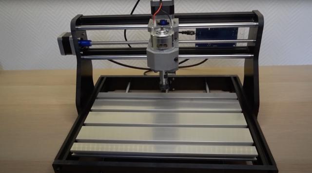
This is a CNC 3018 Pro router. It can be bought for around 150 euros from various online resellers. It comes unassembled. In this tutorial I will first do the unboxing and then share with you my challenges during the assembly of this CNC router.
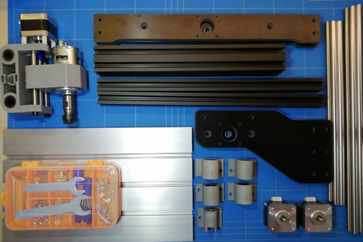
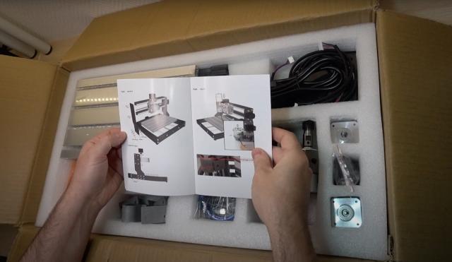
This is the box it came in. All the parts were protected by EPE foam and none of them were damaged. The manual was printed in colour on a good quality paper. The instructions seemed to be clear and easy to understand. The table was protected with a plastic sheet on both sides. The 2040 aluminum T-slot profiles will be used in the assembly of the base. And these 2020 profiles will help support the X-axis. The bakelite parts will be installed on the front and back of the base. And we have various rods and lead screws for the x and y-axes. The power supply is 24 Volts and 4 Ampere. That gives us almost 100 watts of power. We have cables to connect the motors to the controller board. And other bakelite pieces for the sides of the machine. There is also the spindle motor mounted together with the Z-axis stepper motor.
All the needed tools for assembly, screws and the router V-bits are stored here. This box is a keeper. There are PVC moulded parts are to hold the table top for the Y-axis movement. And we have also the controller board and a mini-USB cable. This acrylic plate will hold the controller board and we have some software on an USB stick. There are also parts are to hold your working piece to the t-slot table top. They are made from black acrylic. And finally we have the X and Y NEMA 17 stepper motors. They are almost the same as the ones on my 3D printers.
Looking through the manual that was provided, shows all the steps that need to be followed. First we will need to build the base, then the sides and the X-axis. And finish with the controller board and all the wires. All the pieces like bolts, nuts and tools are inside this double sided closable box. I think that I will use it after the assembly for something...
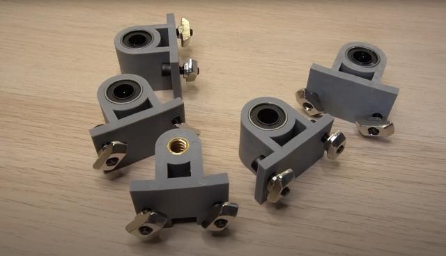
Let's start the assembly by adding the T-slot nuts and bolts to these linear ball bearings covered in PVC. One of the parts has a cutout that will be used for the threaded rod on the Y-axis. The manual mentions using a 16 mm bolt and we shall follow that advice and assemble all the 5 parts. When you look inside the linear bearing, you can see all the small balls lined up. But be very careful, as they are enclosed with plastic and then you insert the rod in the wrong angle they will all break apart.
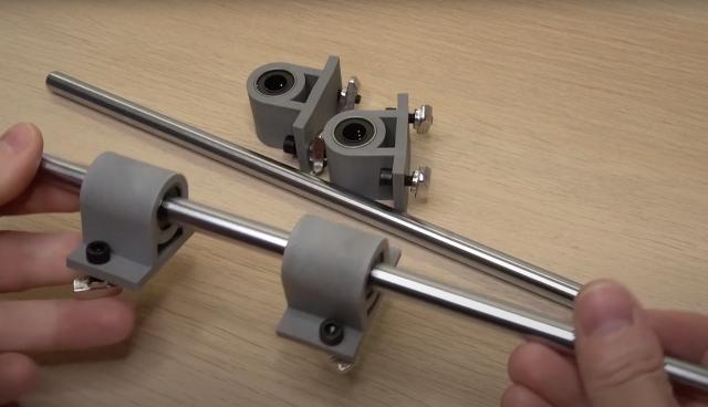
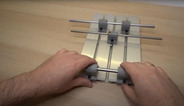
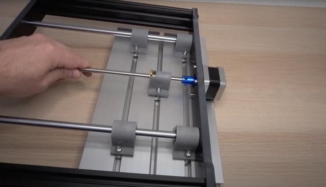
Notice that the bolts are facing outside of the rods. This should provide better stability. The lead screw connects the part that is incised. This lead nut with the spring needs to be pressed inside while rotating the screw. There are 4 and 3 t-slots in the working table. We will be sliding the holders with linear bearing inside them on the side with 3 grooves.
They should slide inside the t-slots like this.
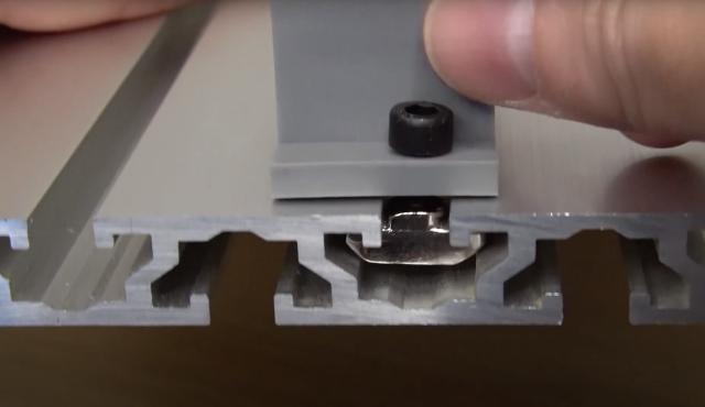
And in the order that I am showing here.
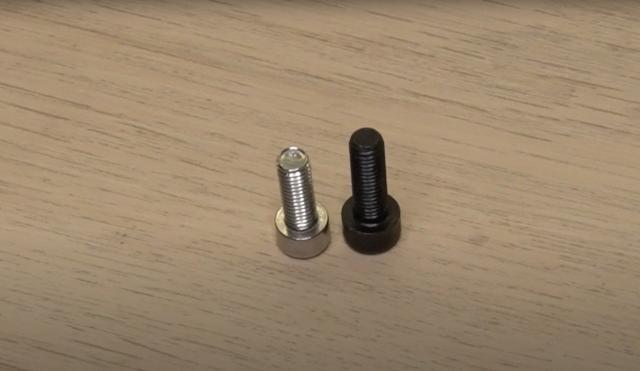
The assembly was provided with 2 sizes of M5 screws. The black ones were 16 mm and the silver ones were a bit shorter. The manual mentioned using 16 mm for those linear bearings, but it did that for all of the other connections as well. I found out that the silver screws were too short to hold the side panels to the t-slots. And there were simply not enough of the longer screws. So I had to swap them here.
This time I inserted the linear bearings before sliding them on the rods. Maybe this way is a bit easier. Let's put the t-slot working table aside and focus on the assembly of the support that will hold it. I have prepared all the parts that will be needed. These are the bakelite (bake a lite) front and back panes and the 2040 T-slots.
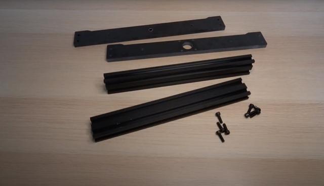
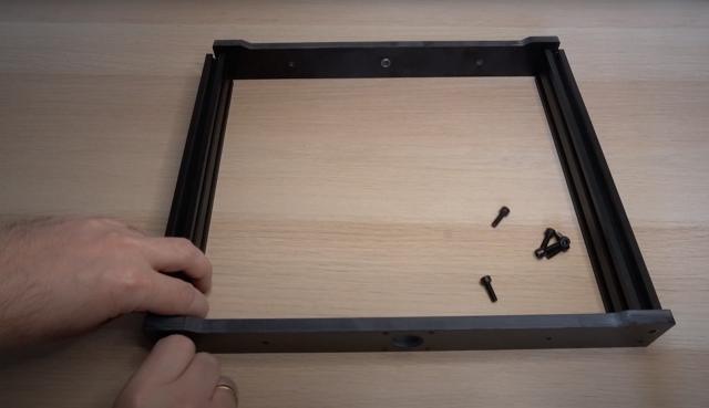
The part that I have put in the front is actually the back of the router. This is also where the Y-axis stepper motor will be attached. Also note that the bakelite plates have predrilled holes for Y-axis rods and they go on the inside. I am now attaching them with the 16 mm screws, but this is a bit premature as we will find out in a minute.
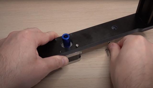
In this step I am attaching the coupler to the stepper motor. It uses 4 small screws that will attach the NEMA 17 stepper motor to the lead screw. And now it can be attached using these M3 bolts to the bakelite plate.
Let's place the table with the rods and try to attach it. But wait.. these side t-slots are a little bit in the way. So let's unscrew them first. Now it is a bit easier to connect the lead screw and the 10 millimeters steel rods. And the back side (I mean front side) needs to be attached as well. It is safe to attach the side aluminium profiles back to the base. However, do not fasten them tight yet. I left a little bit of space between the shaft of the motor and the lead screw and fastened the small screws.
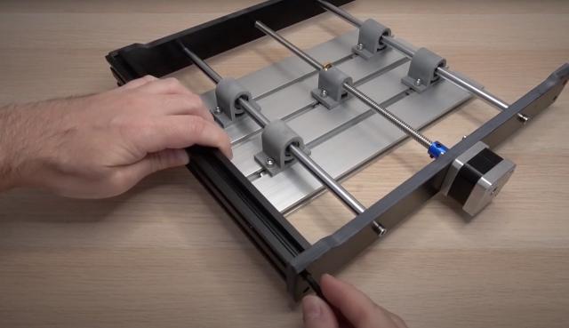
Now it's time to secure the linear bearings to the t-slot working table. This is a bit tricky as they need to be spot on straight. So first I moved the table to the edge of the base, then I have straightened the t-slot nuts, so they can be tightened. You have to be sure that the table is centered. In my case both sides were 1 cm from the edges. The rods need now to be tightened down. Next, I have moved the table all the way, so it was touching the back of the base. It was secured and it could be lifted up without anything moving. I have fastened the center linear bearing and then all the remaining ones.
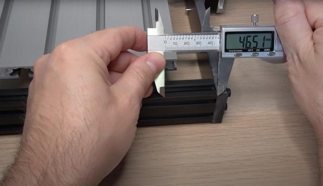
After turning the base around the sides can be secured tightly. The bakelite side panels need to be 46.5 millimeters from the back of the t-slot edge. I forgot to make the marks before fastening them, so I am using the lower jaws of the caliper to make a small scratch. I did that on both sides.
Now we can attach the side panels to the 2080 t-slots. First, the 16 mm bolts need to be inserted into the pre drilled holes in the bottom - together with the T-slot nuts. Align them horizontally in this way so they can fit into the T-slot holes. The T-nut has a particular shape that allows it to rotate and lock when it is fastened. Now the right panel can be fastened as well. Note the distance that we have marked earlier.
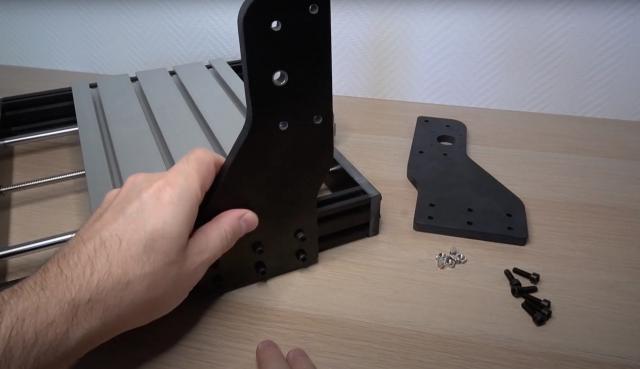
The manual mentions that the stepper motor should be on the right side, but in my version it is located on the left. This probably means that the X-axis needs to be inverted somewhere in the GRBL settings later on. Let's continue and attach the left panel in the same way as before.
Next we need to attach the x-axis stepper motor. This is also done in the same way as on the Y-axis.
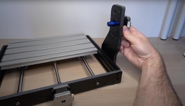
But wait a second... the rod does not fit like this. What was I thinking... let's untighten the left side panel.
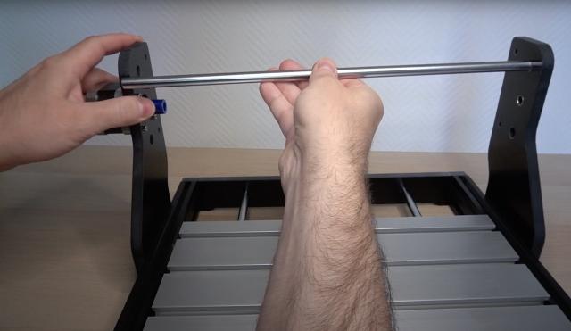
We can now attach the lead screw to the last and the most important part of this CNC machine, which is the spindle motor with the Z-axis. This is done the same way as before. Proceeding now with the insersion of the 10 mm rods, and the attachment of the left side panel.
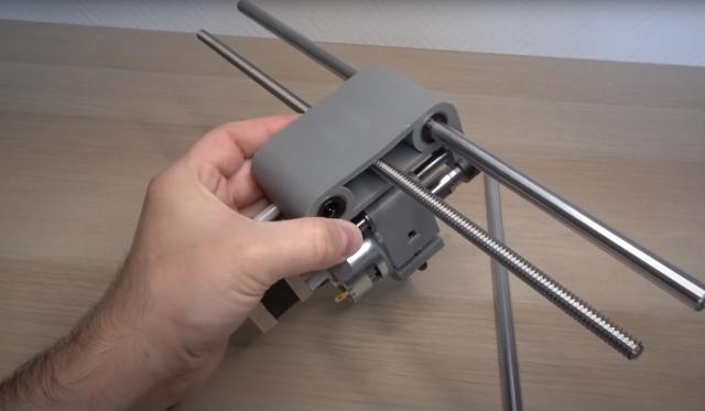
I think that we might have a show stopper as the lead screw does not fit inside the hole. No worries there...
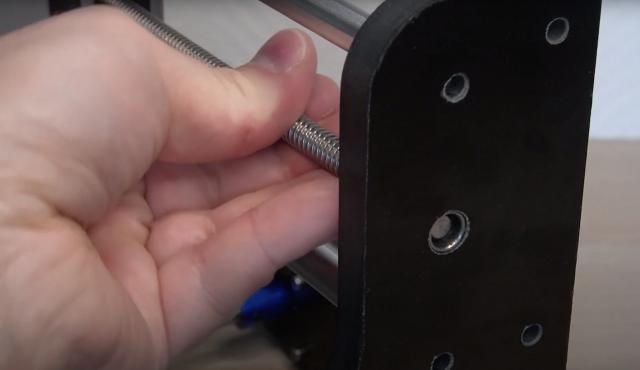
I am sure the support department where I have bought this machine will give me some advice. And they did...

Well.. it might work, but I've decided to try to make the hole bigger by using a round file. I was pushing the file up and down.. I mean.. forward and backward.. ehhm... anyway. Then I used some fine sandpaper to smoothen the hole. The rod fitted now and could slide freely.
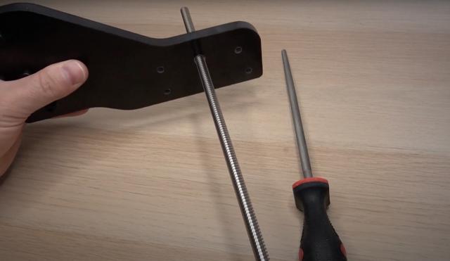
This time without the lead screw I have placed the spindle motor between the side panels. And finally attached the lead screw. The 2020 t-slots can now be attached to the back using the shorter silver M5 screws. We will also tighten the metal rods in the same way.
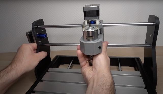
It is time to finish up the assembly and install the controller board. It will be sitting on top of this acrylic plate. First let's rinse the board using isopropyl alcohol and dry it off with a paper towel. The board can now be attached with the provided M3 bolts and these shot M5 screws.
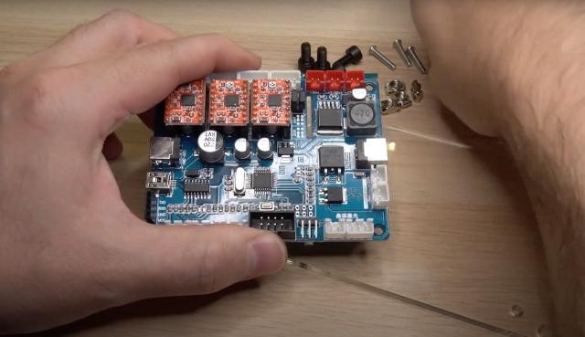
Before fastening it down, I just wanted to see how it will fit. And.. it doesn't. So I had revered the M3 screw in a way that the nut was on top ... and this time it fitted perfectly. I thought that attaching the board on the right side was a good idea as the x-axis stepper motor was also there. I really like the locking mechanism on these t-nuts.
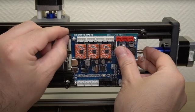
The controller board has a marking DQ-CNC-TS-9272-V3, that's quite a mouthful. It has these 3 stepper motor drivers. And is running on an atmega 328p chip, which is the same as on an Arduino board. We can proceed connecting all the cables. Above the stepper motor drivers you can barely see the labels, but this will do.
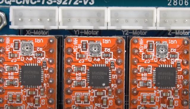
First we connect the x-axis, then Y-axis and finally the Z-axis.
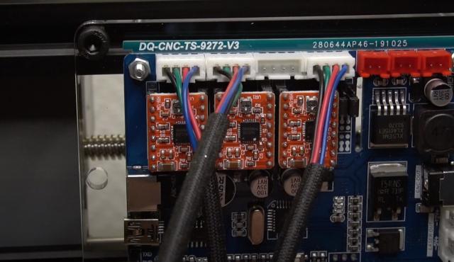
The spindle motor cable needs to be connected to the CNC OUT port on the board and to the motor itself.
One of the sides has a red dot, this is where the positive wire will be connected.
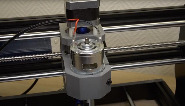
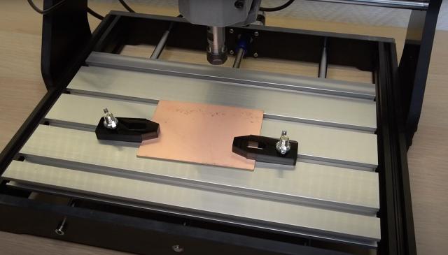
Famous last words. It is done. Oh wait.. there are still these acrylic table clamps that need to be assembled. Let's do that quickly. They will hold this PCB nicely in place, that I will hopefully mill in the future.
The router bits were also stored in this orange box. It would be nice to have them in a separate container, but this will do for now... What kind of routing bits were supplied? This one is a V-bit. And this was as well... Actually they were all V-bits.
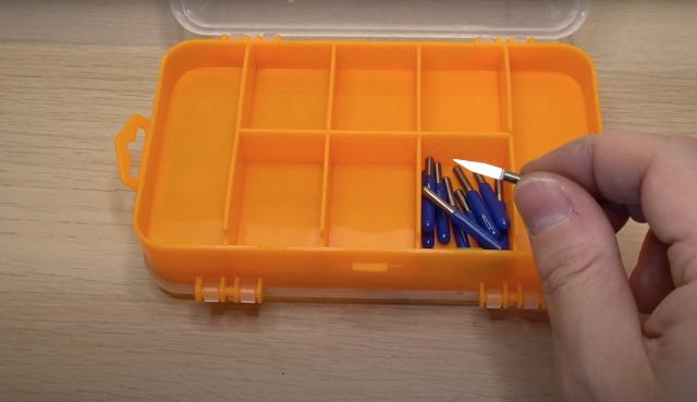
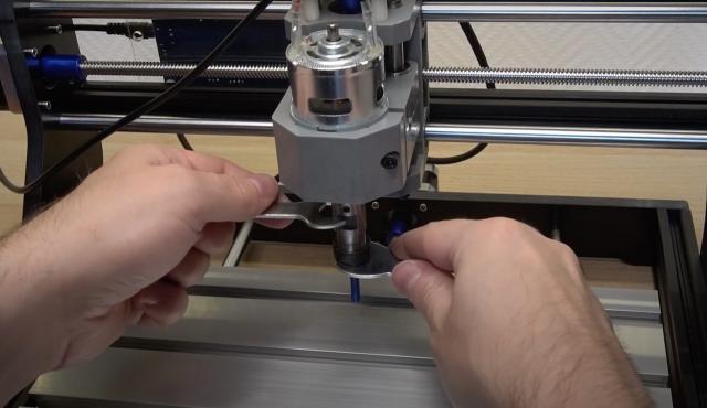
Let's try to attach one to the router. This fits nicely.. and we can tighten it down using these two provided wrenches.
Connecting the power supply lights up a red LED on the board, so that looks promising. I have decided to change the controller board to the other side. The power and USB connections are there as well, so I think it will be better like this. In a future video I will try to mill a PCB with this CNC router.
