In this blog post I will be showing a couple of examples of what you can do with it and explore some of the expansion boards that can be used to create some fun projects.
I am starting this blog post with the logo of Acorn Computers, which in my opinion is one of the most influential names in computing history. Not only have they dominated the past with the BBC Micro and other Acorn computers, but they are also the creators of the ARM architecture which is still in use today.

In the 80's Acorn Computers cooperated with the BBC to create the BBC Micro for the Computer Literacy Project and once again, now operating under the name Element 14 they have partnered up with the BBC to create the micro:bit board.
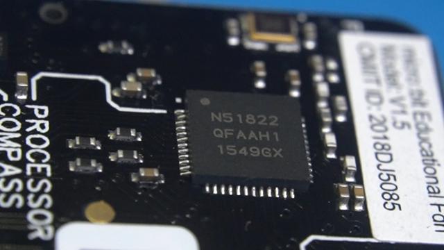
The heart of it is this tiny 32-bit ARM Cortex-M0 CPU with 256 KB of flash, 16 KB of RAM memory and bluetooth support.
This project was made possible by Digitspace.com that donated a couple of the micro:bit products.
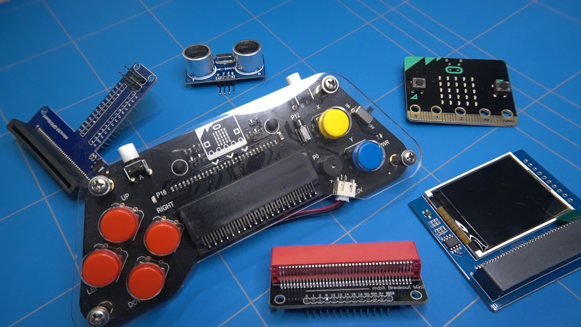
Let's see what I received:
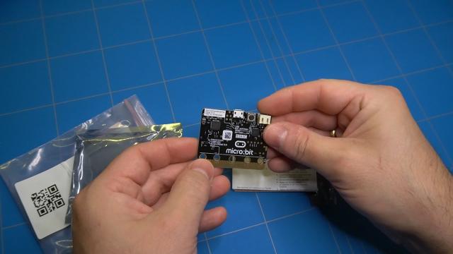
To start with there was the micro:bit board. It was nicely packed in an anti-static bag.
It also contained a safety guide and a getting started manual.
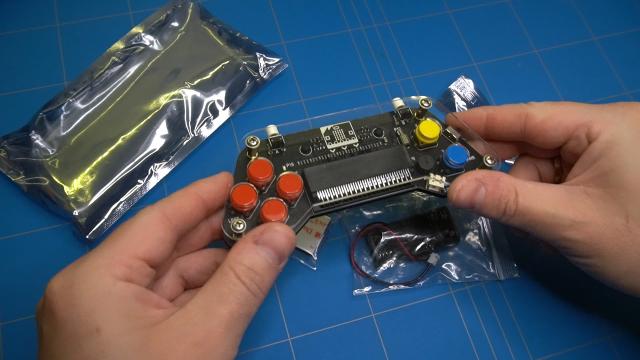
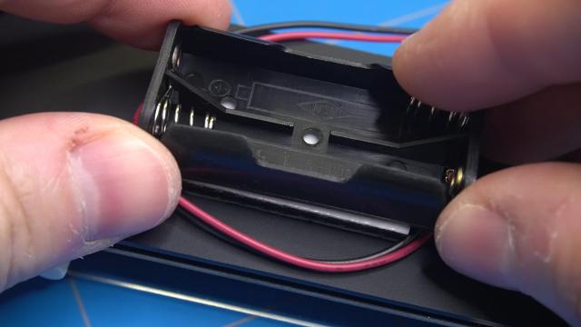
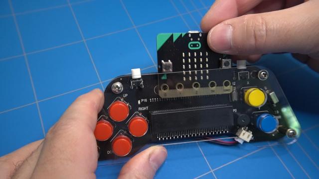
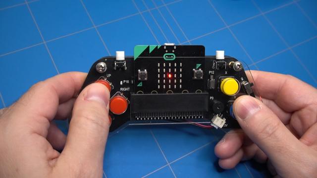
The next product was an expansion board in the form of a game pad. It included a battery holder with connector and a double sided adhesive sticker to glue it on the back.
There was also this nice T-Shape breakout board to connect the micro:bit to the breadboard.
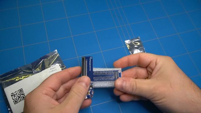
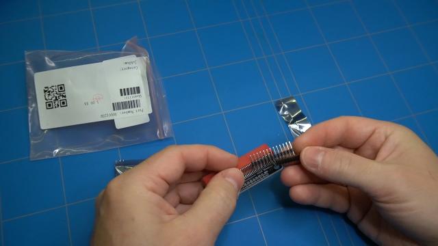
And another breakout board which was a bit smaller. It had two kinds of connectors, one for vertical and the other for horizontal mounting on the breadboard that had to be soldered. Which I did.
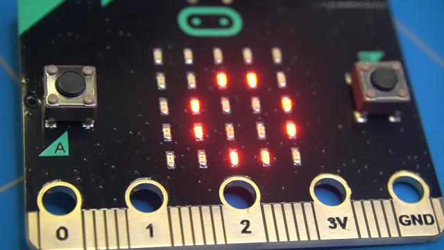
To begin with I have connected the micro:bit board to USB as there is usually a welcome or blink LED project preinstalled. And in this case it was a Hello World message.
Before we start creating something ourselves let's assemble the game pad expansion board and add the battery connection to the back of the controller, this way we will be able to play our games without the need of a USB cable. The double sided tape is quite strong, so make sure you get it right the first time.
The micro:bit has 2 tactile switches which can be used to control your sketches, but if you need more buttons, then this game pad will give you that option.
It also has a Vibration motor, a blue LED and a small speaker.
It would be a good idea to first test if it works. We can do that by inserting the micro:bit board, placing 2 triple A batteries inside the holder and turning it on. We can still see that the hello world sketch is still working.
Now, let's see if we can create something on the micro:bit as this hello world is getting a bit boring.
After we connect the micro:bit to the computer using USB cable, it's ready to go. I am using a Mac and there was no need to install any drivers. We can also see that a new drive called MICROBIT will pop up. When we open it, two files can be found. One of the files is called DETAILS.TXT and it shows information about the board, like which version of the firmware and bootloader is installed.
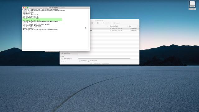
The other file is a web link to the micro:bit website showing how to get started using the board.
Deleting the files will not break anything as they will be recreated the next time you will reconnect the micro:bit to USB. It is also possible to upgrade the firmware to the latest version. I have included a link in the description on how to do it.
To write your own program you need to click the link let's code and this will give you a choice between using makecode editor or python. But before we do any of that let's try to upload an existing game to our micro:bit.
On the youtube channel of Hay Kel there is a link to the Pong game.
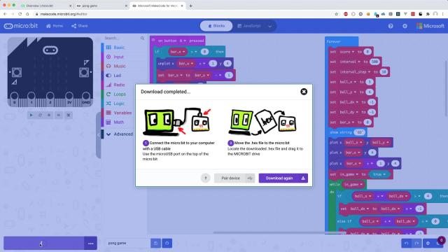
When you click on it, you will be shown this screen with the full code of the game in blocks. Clicking on the edit link, will open the game in the microcode editor. When we click on the download button, a popup will show up asking to pair our device. Then after we select it, we need to click on the download button again so the code will be uploaded to the micro:bit. I am not sure why the term download is used as we are actually uploading the code to the board.
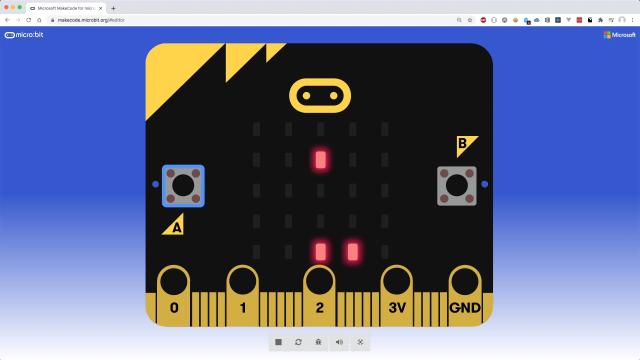
It is also possible to play the game in the emulator as it only uses 2 buttons to move the paddle left and right, but let's try to play the game on the gamepad. The 2 buttons on the top refer to the A and B buttons on the micro:bit.
We can now go back to the code editor and create something ourselves that will utilize all the buttons on the controller.
Full documentation on how this expansion gamepad board works can be found on this page. It mentions that we first need to add an extension to our project using this Github repository: https://github.com/DFRobot/pxt-gamePad
After we have done so, inside the blocks list a new selection will appear called gamepad.
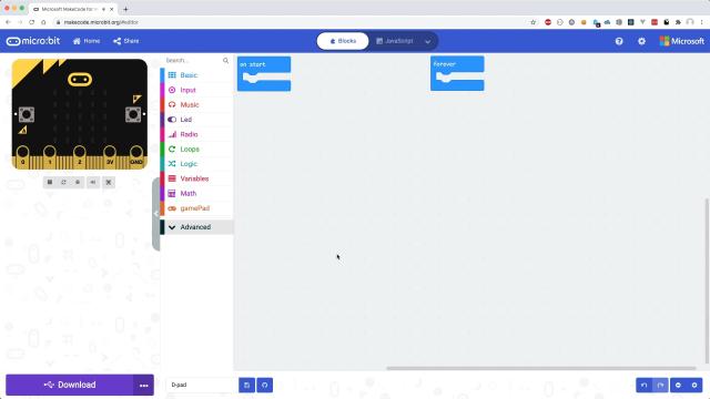
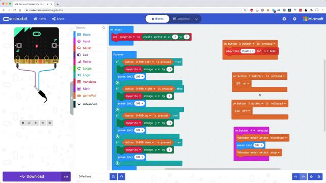
The editor has 2 blocks placed by default, which are "on start" and "forever". If you are familiar with Arduino IDE sketches, they are the same as setup and loop functions.
First we will make a variable that represents a sprite and is actually a LED dot. This is placed inside the start block.
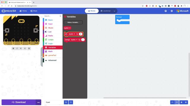
Using the game blocks we can create that sprite at a given position and assign it to a variable.
When we now click on our imported gamepad extension, some blocks will appear that we can use to control the buttons.
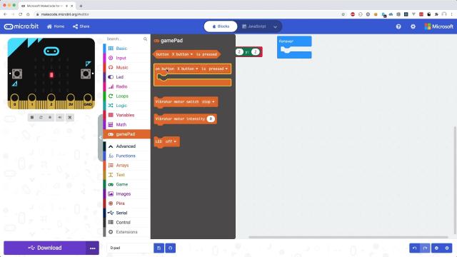
Selecting this "on button block" will allow us to listen to an event on one of the buttons of the gamepad. We will start with the d-pad up button
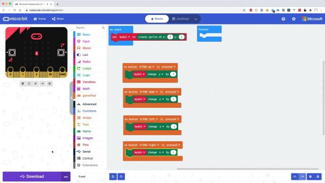
Inside the game group we can select the "sprite change" block that will allow us to change the Y position of our dot by an offset of -1.
We can quickly do this for the remaining buttons on the d-pad like d-pad down, d-pad left and d-pad right. Changing the relative offset from Y to X.
After uploading or downloading the code to the micro:bit we can test it.
The dot sprite appears to react to all of the d-pad buttons presses.
Let's finish up our test code by adding support to the remaining buttons and triggering the vibration motor, led and the buzzer. Notice that I have also changed the handling of the d-pad buttons by using the if statements. This allows continuous sprite movement when a button is held down.
Uploading the sketch and testing it shows that everything is working.
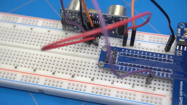
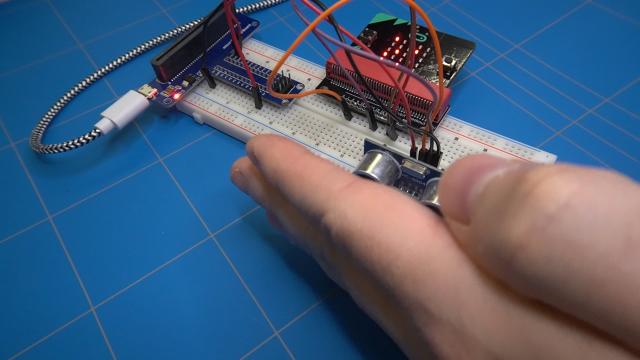
Let's move on and make another small setup with the breadboard and one of the breakout boards.
So here we have our breakout board that connects to the micro:bit board. We can stick it into the breadboard.
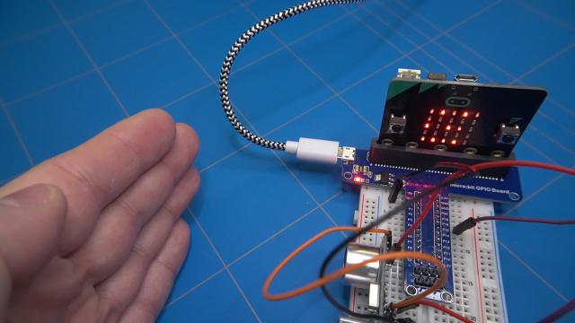
We will use this ultrasonic sensor to get a reading in centimeters that will show up on the micro:bit LEDs display.
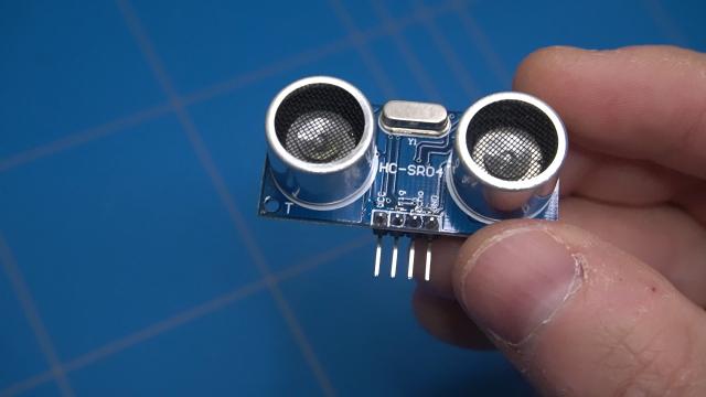
I am basing this project on a blog post from the osoyoo.com website. It describes how the ultrasonic sensor works and shows some formulas on how to calculate the distance of an object to the sensor using the speed of sound.
To connect the sensor we need 4 jumper wires.
The micro:bit board uses 3 Volts so we need to use the 5V pin of the breakout board to supply power for our sensor. The other wire connects to ground.
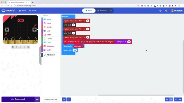
The 3rd wire connects P8 to the trigger pin and the last wire P16 to the echo pin of the sensor.
We can see that P8 is reset to logical 0 and then after 2 microsecond pulled high for another 10 microseconds. This triggers the sensor to make an ultrasonic burst signal.
The block below reads the burst pulse that is bounced off an object on the P16 pin and calculates the distance in centimeters.
This distance is shown on the display.
Now we can connect the micro:bit board using USB to the computer and upload the sketch.
But wait a minute. It is not working.. The display shows 0 all the time. It seems that the power is not passed through to the breakout board. And it actually makes sense as the 3 Volts can not be stepped up to 5V from the micro:bit board to the breakout board. The other way around it is possible.
So let's connect the power to the micro usb connector on the breakout board and check again. Now when I move my hand away and back towards the sensors it shows a change in the distance.
I have also connected the other breakout board to and it worked as well. I think that I like the first breakout board more as it also has a micro usb connector and a 5V output.
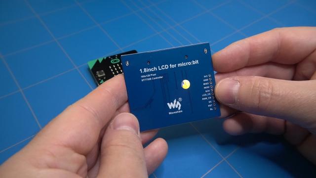
As the last project I wanted to show you this 1.8 inch LCD screen. I have bought this display myself when looking at some other modules for micro:bit.
It also needs an extension for the blocks editor and a link to the github repository can be found on this website. A manual on how to use it can be found there as well.
The extension is added in the same way as before. By clicking on the extension we can see all the possible blocks that can be added.
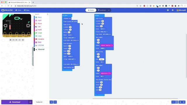
To test this screen I have created a small sketch that prints the temperature and the compass heading inside a square and a circle.
Let's quickly go through the code. In the beginning we need to initialize and clear the screen. Then a circle and a rectangle is drawn with blue and green outline color. This data needs to be sent to the display using the "send display data" block.
The forever block starts by drawing a smaller white circle inside the circle with a green outline. This is to clear what was previously written inside of it. Then the compass heading and the temperature is printed.
The update of the screen is rather slow, so you can select a portion of the display to refresh. This is done using the "Show window display data" block.
Let's connect the display to the micro:bit board and upload the sketch.
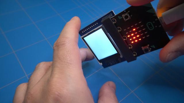
After it is finished uploading the text TILT TO FILL SCREEN showed up. I had no clue what it meant as this was certainly a part of my uploaded sketch. Then I quickly realized that the compass needed to be calibrated before first use.
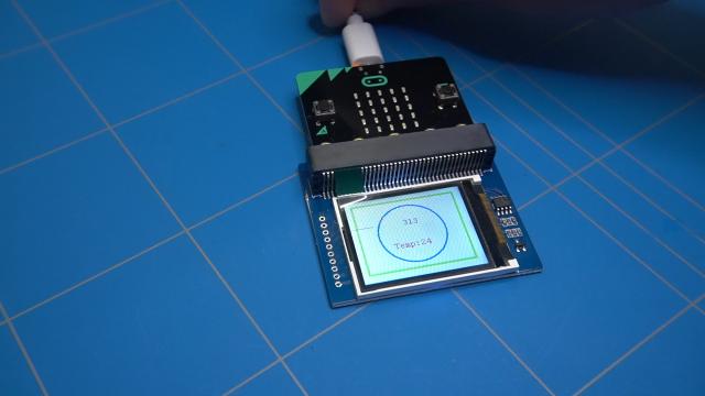
So I tilted the micro:bit until all the dots filled the screen. And the connected LCD display started to show the output.
Rotating the screen showed the current heading. Good to know that the camera was pointing the direction around 300, which is North West.
To conclude, the micro:bit is a very fun board to play with that gives a lot of possibilities in creation of small electronics projects. We have barely scratched the surface here. Micro:bit also allows you to write programs in MicroPython.
Thank you for reading this post and sticking to the end. I hope you have learned something about the micro:bit board. If you have any questions please contact me.