18650 batteries are known for it's high energy density, but this comes at a price. In order to protect the battery from overcharging or over-discharging a number of ICs need to be used. Luckily these charge and protector circuit boards are readily available for sale in all shapes and sizes. In this blog post I am going to build a charger that uses such a circuit.
Not only the charger can use protection circuitry, but also the battery itself. When buying the batteries make sure that they are protected. I have bought mine in a Chinese online webshop.
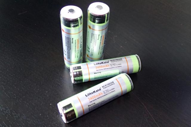
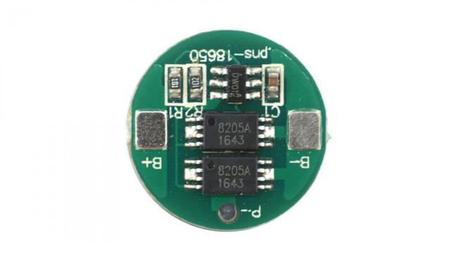
They have a battery protection PCB connected to the negative terminal containing a DW01 chip and 2 MOSFETs.
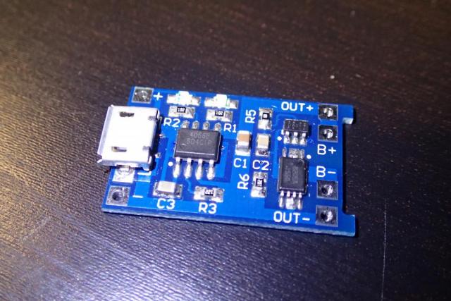
The board that is used in the charger has the same protection ICs as the battery and a TP4056 Linear Li-lon Battery Charger chip which is meant to manage the charging of the battery. It is of course an overkill to use double protection circuitry on the battery and on the charger, but when you are using the battery in stand alone mode (outside the charger) it comes in handy. When you are planning to always use the 18650 battery from within this charger you don't need the extra protection on the battery itself.
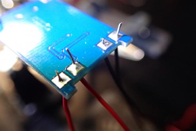
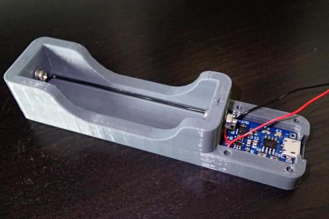
I have started to solder wires in order to be able to connect the battery and as an extra feature I have added wires for the output terminals.
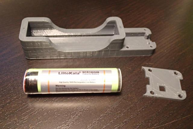
I have found a design on thingiverse that encompasses the battery and the board, but it was a bit too small for my TP4056 board version, so I made some modifications to it. I guess that mine has an micro USB connector and the designed one was for mini USB board. Searching on "tp4056 protection" will show you the difference. If you have the micro USB version (with the overhangs in the back of the board) you can download my modified design on Thingiverse.
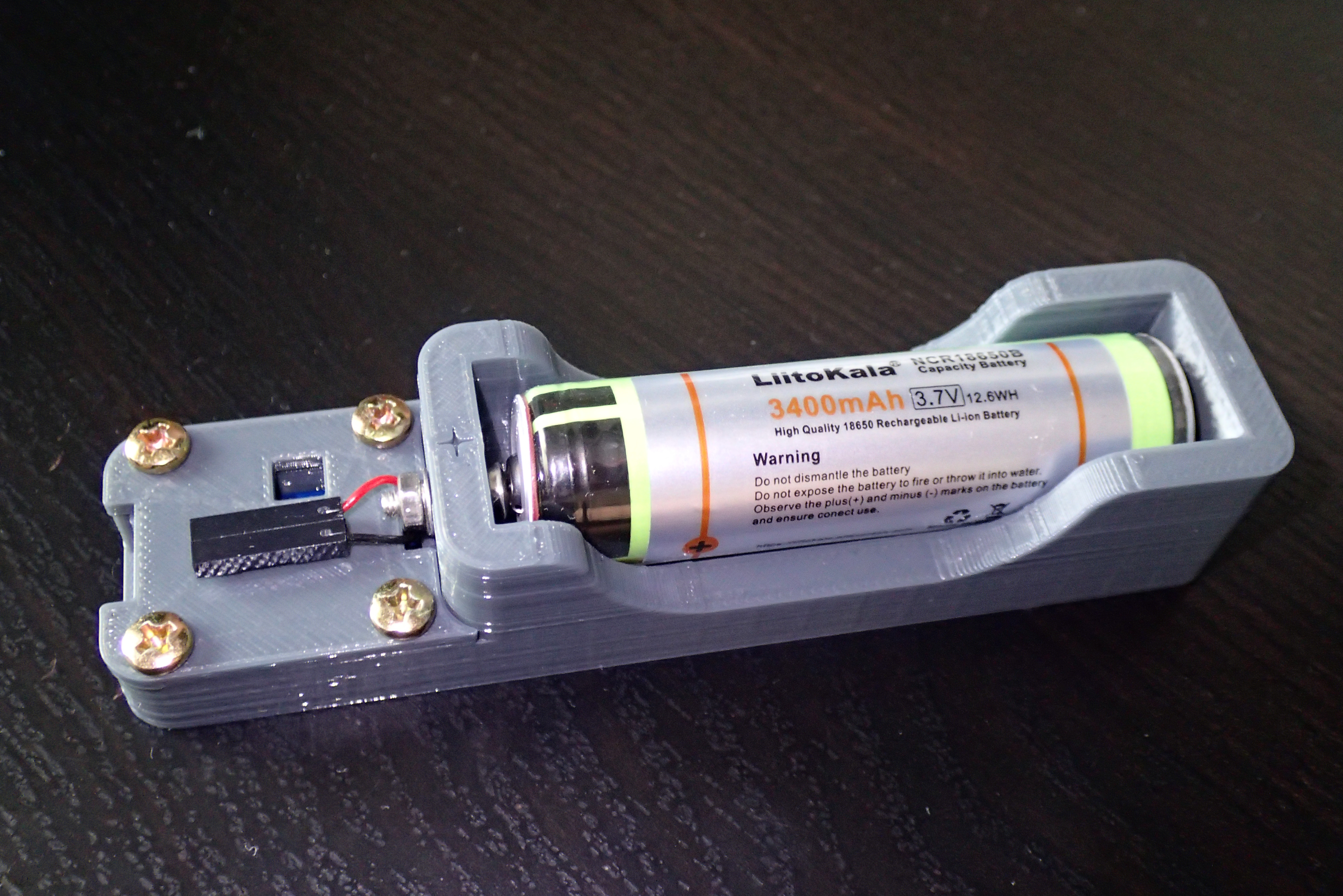
After inserting the board into the case you just need to strip the soldered wires and cut them to the desired length. The B+ wire is very short and it attaches to the screw directly above it. The negative (B-termial) can pass through the hole to the other M3 screw...
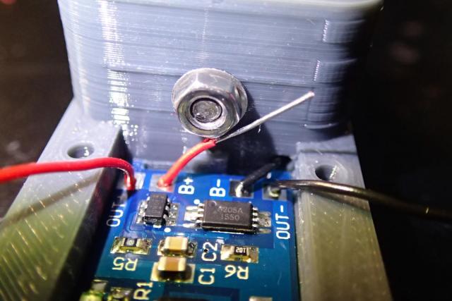
... and can be connected on the negative side. Because my 18650 battery had a protection circuit it was a bit longer and I did not need to connect any springs. Adding a washer was just enough and the battery fitted in tightly.
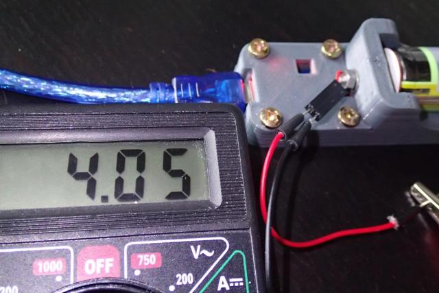
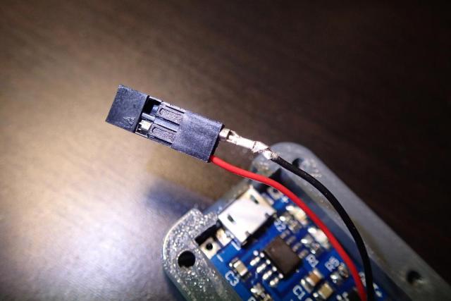
On the output wires I have added an dupond jumper wire housing. The output will be around 3.7V, but in the future I can connect a booster module to get more voltage out of the battery.
A fully charged 18650 battery is around 4.2V. I have measured the voltage during the charging process and it was around 4V. After the battery was fully charged the blue LED turned on. It measured a voltage of 4.15V